
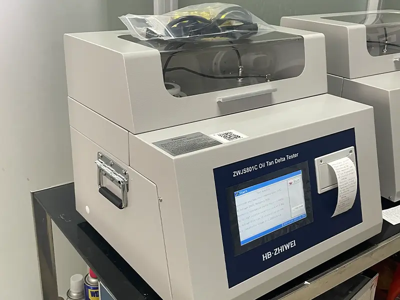
In large liquid-immersed power transformers, instrument transformers, and oil-filled bushings, insulating oil serves two critical functions: providing primary electrical insulation against tens of thousands of volts and dissipating heat generated by the iron core and windings.
However, during preventive maintenance tests and in oil testing laboratories, many engineers encounter a perplexing issue: some transformer oils pass routine Breakdown Voltage (BDV) tests, yet the equipment still suffers from localized overheating or even insulation breakdown shortly after being put into service. The root cause lies in polar soluble impurities, colloids, and metallic microparticles generated during long-term thermo-oxidative aging or moisture ingress. Capturing this early-stage, nanoscale chemical deterioration requires high sensitivity—which can only be achieved through Insulating Oil Dielectric Dissipation Factor (tanδ) and DC Volume Resistivity (ρ) testing in accordance with the IEC 60247 standard.
This article provides an in-depth breakdown of the underlying physical mechanisms of oil dielectric loss and resistivity, as well as the design principles behind the three-electrode oil cell. Combining these concepts with a recent remote international acceptance test conducted for a client in Chile using the ZWJS801C Insulating Oil Dielectric Loss Tester, we will demonstrate how to interpret test printouts, perform a standard “Empty-Cell Calibration Test,” and follow standardized cleaning procedures for the oil cell.
Why Test Insulating Oil Dielectric Loss (tanδ) and Volume Resistivity (ρ)?
1. The Physical Nature of the Dielectric Dissipation Factor
Under an alternating electric field (50Hz/60Hz), ideal, pure insulating oil behaves as a pure capacitor. The current I flowing through the oil gap should strictly lead the applied voltage U by a phase angle of 90°, resulting in zero active power loss.
In real-world applications, however, polar molecules within the oil (such as organic acids, aldehydes, and ketones produced by aging), free water, and conductive ions undergo dipole orientation polarization loss and conductive leakage loss under an alternating electric field. This causes the total current to deviate from the ideal capacitive current by an angle δ (known as the dielectric loss angle). The ratio of the active loss current component IR to the reactive capacitive current component IC defines the dielectric dissipation factor, tanδ:
ω = 2πf is the angular frequency, Rp is the equivalent parallel insulation resistance of the oil gap, and Cp is the equivalent capacitance of the oil gap.
2. The Complementary Diagnostic Value of DC Volume Resistivity
When a stable direct current (DC) voltage is applied across the three-electrode oil cell, alternating polarization losses are eliminated. The measured volume resistivity ρ (unit: Ω·m or TΩ·m) then directly reflects the migration concentration of free conductive ions within the insulating oil.
Based on the geometric relationship between standard parallel-plate capacitance and resistance, the formula for calculating volume resistivity ρ is:
Note: Where Ca is the geometric capacitance of the empty electrode cell, ε0 = 8.854×10⁻¹² F/m is the permittivity of vacuum, and Rx is the DC insulation resistance of the oil sample measured after 60s of voltage application.
Engineering Diagnostic Conclusion: A smaller tanδ and a larger volume resistivity ρ indicate higher purity and superior anti-aging performance of the insulating oil.
When insulating oil is contaminated by trace amounts of fiber impurities, aged sludge, or polar chemicals, tanδ and ρ will exhibit order-of-magnitude changes even before the breakdown voltage (BDV) shows any noticeable decline—offering a sensitivity several times higher than dielectric withstand voltage testing!
Understanding IEC 60247 Standard Test Conditions: The Three-Electrode Oil Cell and Four Core Parameters
To ensure strict repeatability and comparability of oil dielectric loss data across different laboratories worldwide, the international standard IEC 60247 defines both the physical structure of the test cell and the electrical excitation parameters:
1. Why Must a “Three-Electrode Oil Cell“ with a 2mm Electrode Gap Be Used?
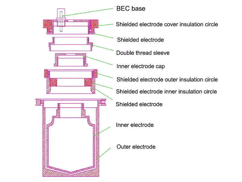
As shown in the diagram above, the oil cell used in precision oil dielectric loss testers like the ZWJS801C is far more complex than two simple metal cylinders. Instead, it is a coaxial three-electrode system consisting of a high-voltage outer electrode, a low-voltage inner measuring electrode, and an upper annular guard electrode:
Eliminating Fringe Field Distortion and Stray Capacitance: The guard electrode tightly surrounds the low-voltage measuring electrode, ensuring that the electric field lines between the high-voltage electrode and the measuring electrode maintain an absolutely uniform radial distribution. This completely eliminates capacitance errors caused by fringe effects.
Bypassing Insulator Surface Leakage Current: Any minute creepage current across the surface of the PTFE insulation ring supporting the electrodes is directly intercepted and shunted to ground by the guard electrode (grounded terminal), bypassing the measurement sampling circuit. This ensures that the measurement reflects 100% pure bulk loss of the insulating oil itself.
2. Four Core Parameters of the Standard Test
Under the IEC 60247 standard test mode, the instrument automatically executes four core benchmark parameters:
Standard Test Temperature: 90°C (Utilizing medium-frequency induction non-contact uniform heating to precisely maintain the oil temperature at a constant 90°C);
AC Test Field Strength: 1000V/mm (Since the standard electrode gap of the three-electrode oil cell is d = 2mm, the instrument automatically applies a 2000V AC power-frequency sinusoidal voltage, i.e., 2000V / 2mm = 1000V/mm);
DC Test Field Strength: 250V/mm (Applying a 500V DC high voltage across the 2mm gap);
DC Polarization Charging Time: 60s (Applying the DC voltage for a full 60s to allow oil gap capacitance charging and absorption current decay to complete before reading the steady-state conduction current to calculate volume resistivity ρ).
Overseas After-Sales Case Study: How to Verify Instrument and Oil Cell Accuracy via the “Empty-Cell Test”?
For overseas power laboratories procuring high-voltage testing equipment internationally, two major concerns often arise: “After enduring tens of thousands of kilometers of ocean or air freight vibrations, can the internal standard capacitor and precision oil cell still maintain factory-grade accuracy? And if operational questions come up, can the manufacturer provide timely, professional technical support in English?”
Below is a real-world record of a remote international unpacking and acceptance test conducted on October 21, 2026, by our after-sales engineering team with Mr. Pablo, a power laboratory client in South America (Chile).
1. Case Background: The First Critical Threshold Before Testing Oil — The Empty-Cell Test
After the Chilean client received the ZWJS801C Insulating Oil Dielectric Dissipation Factor and Volume Resistivity Tester, and prior to injecting any transformer oil samples, our after-sales engineers guided him through a dedicated technical support group to first perform the IEC 60247 standard empty-cell calibration test.
Why test the empty cell first?
Before filling with oil, the 2mm electrode gap of the three-electrode oil cell uses dry air as the dielectric medium. Because pure air has an extremely low dielectric loss (theoretically approaching 0) and a relative permittivity of εr ≈ 1.0006, heating the empty oil cell to 90°C and applying full AC and DC high voltages serves two vital purposes:
On one hand, it precisely determines the geometric reference capacitance Ca of the empty cell (which is required for subsequent calculations of the oil’s relative permittivity εr = Cx / Ca and the resistivity cell constant k);
On the other hand, it acts as the ultimate litmus test to verify whether the oil cell was exposed to moisture or contamination during transit and assembly, whether the PTFE insulation ring remains clean, and whether the sampling accuracy of the instrument’s internal standard capacitor is fully intact!
2. Line-by-Line Breakdown of the Client‘s On-Site Thermal Printout
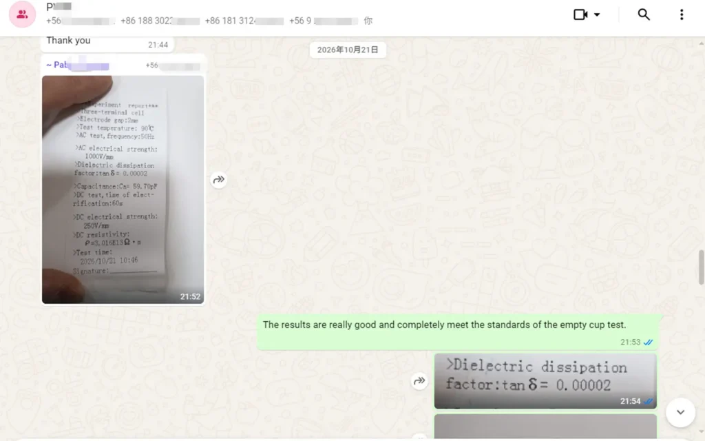
Immediately after completing the fully automatic 90°C heating and sequential AC/DC tests, the client photographed the receipt printed by the instrument’s thermal printer and shared it in the support group. Let’s analyze this actual test report line by line from a technical perspective:
| Evaluation Parameter | Manual Standard Acceptance Criteria | Client’s On-Site Measured Value | Technical Evaluation of Accuracy & Performance |
|---|---|---|---|
| Empty-Cell Capacitance (Ca) | 60pF±5pF (55~65pF) | 59.70pF | Deviation of only 0.30pF (0.5%), indicating exceptional coaxial machining and assembly precision. |
| Empty-Cell Dielectric Loss (tanδ) | ≤0.00010 (0.01%) | 0.00002 (0.002%) | Measured value is just 1/5 of the upper limit, demonstrating 0.00001-level resolution and superior cleanliness. |
| Empty-Cell DC Resistivity (ρ) | Extremely High Insulation (≥1.0×10¹³ Ω·m) | 3.016×10¹³ Ω·m (30.16TΩ·m) | Exceeds 30TΩ·m even at 90°C; shielding and insulation design effectively isolate high-temperature leakage currents. |
Acceptance Criteria for Transformer Insulating Oil: Quick Reference Table of Permissible Limits for New and In-Service Oils
Once the “Empty-Cell Test” is successfully passed and the calibration parameters are automatically saved, the transformer oil sample can be injected for testing. What measured values qualify an oil sample as acceptable?
According to the IEC 60422 testing guidelines, the acceptance criteria for oil-filled electrical equipment across different voltage ratings at the standard temperature of 90°C are summarized below:
| Equipment Voltage Rating | Oil Sample Category | 90°C Dielectric Dissipation Factor (tanδ) Limit | 90°C Volume Resistivity (ρ) Limit | Recommended Engineering Action for Abnormalities |
|---|---|---|---|---|
| 500kV and Above EHV/UHV Transformers | New Oil Prior to Commissioning | ≤0.005 (0.5%) | ≥6.0×10¹⁰ Ω·m | If new oil fails to meet limits, filling is strictly prohibited; perform high-vacuum degassing/dehydration or adsorbent reclamation. |
| 500kV and Above EHV/UHV Transformers | In-Service Oil | ≤0.015 (1.5%) | ≥1.0×10¹⁰ Ω·m | If tanδ > 1.5%, localized dielectric overheating may occur; immediately test moisture content and acid number in oil. |
| 110kV~330kV Main Transformers / Instrument Transformers | New Oil Prior to Commissioning | ≤0.007~0.010 (0.7%~1.0%) | ≥5.0×10¹⁰ Ω·m | Evaluate comprehensively in conjunction with equipment partial discharge tests. |
| 110kV~330kV Main Transformers / Instrument Transformers | In-Service Oil | ≤0.020 (2.0%) | ≥5.0×10⁹ Ω·m | When dielectric loss approaches 0.020, shorten preventive test intervals and schedule online oil filtration or oil replacement. |
| ≤35kV Distribution Transformers & Switchgear | New Oil Prior to Commissioning | ≤0.010 (1.0%) | ≥1.0×10¹⁰ Ω·m | Routine acceptance metric. |
| ≤35kV Distribution Transformers & Switchgear | In-Service Oil | ≤0.040 (4.0%) | ≥1.0×10⁹ Ω·m | Indicates severe oxidative deterioration of the oil; oil replacement is recommended. |
Note: Industry convention often expresses tanδ as a percentage by multiplying by 100% (e.g., recording 0.005 as 0.5%). Please pay attention to numerical format conversion when reading the instrument’s printed receipt (which displays values in decimal form, such as 0.00002).
Details That Make or Break the Test: Standard Cleaning and Dust-Free Assembly Protocols for the Three-Electrode Oil Cell
Based on years of technical support statistics, over 90% of cases involving “excessive empty-cell dielectric loss (>0.00010)” or “erratic repeatability on the same sample” are not caused by hardware failure. Instead, they occur because the electrode cell was not thoroughly cleaned or the operator touched the inner electrode with bare hands!
To achieve an optimal baseline like the tanδ = 0.00002 result obtained by our client in Chile, please strictly follow the standardized cleaning and assembly protocols below:
1. Standard 6-Step Deep Cleaning Method (For First Use, After Testing Degraded Oil, or When Empty-Cell Limits Are Exceeded)
In accordance with the user manual and IEC 60247 specifications, the complete chemical cleaning procedure is as follows:
- Step 1 (Complete Disassembly & Initial Wash): Completely disassemble the oil cell in sequence, and clean all components using chemically pure petroleum ether (boiling range 60–90°C) and benzene (or toluene).
- Step 2 (Solvent Rinse & Degreasing): Rinse all components with acetone, followed by a thorough wash using a neutral detergent.
- Step 3 (Boiling in Cleaning Solution): Immerse all components in a 5% trisodium phosphate distilled water solution and boil for 5 minutes, then rinse repeatedly with distilled water several times.
- Step 4 (Deep Boiling in Pure Water): Place all components into pure distilled water and boil for at least 1 hour to completely remove residual ions and impurities.
- Step 5 (High-Temperature Constant Drying): Place the washed components into an oven maintained at 105–110°C and dry for no less than 1 hour.
- Step 6 (Cooling & Assembly): Once all components have cooled down until they are safe to touch, put on clean gloves and assemble the oil cell according to the protocol, ensuring a reliable connection between the RF test socket core wire and the test electrode.
2. “Simplified Cleaning & Same-Oil Rinsing Rule” for Routine Daily Testing
When conducting on-site tests at a substation or performing routine daily testing on large batches of similar new oil samples, there is no need to execute the time-consuming boiling procedure every single time. You can adopt the following efficient approach:
Routine Simplified Cleaning: Skip the boiling processes in Steps 3 and 4 above. After degreasing with organic solvents (petroleum ether/acetone) and rinsing multiple times with distilled water, place the parts directly into a 105~110°C oven to dry for 1 hour.
No-Wash Method for Continuous Testing of High-Grade Oils of the Same Type: When continuously testing unused new oil samples from the same batch, as long as the previously tested oil sample performed better than the specified acceptance limit for the upcoming sample, there is no need to disassemble and wash the oil cell between tests!
Simply pour out the previous oil, thoroughly rinse (flush) the oil cell at least 3 times directly using the next oil sample to be tested, and then fill it with the new sample to proceed. Conversely, if the previous sample was degraded waste oil with high dielectric loss, you must completely disassemble and clean the oil cell and re-verify the empty-cell test before the next measurement!
3. The 7-Step Dust-Free Assembly Protocol for the Three-Electrode Oil Cell
After cleaning and drying, the surfaces of the oil cell components are in an ultra-clean, high-insulation state. Never touch the electrode surfaces directly with bare hands (if trace sweat, oils, or salts from your fingers contaminate the inner electrode, the empty-cell dielectric loss will spike tens of times instantly at 90°C). Always wear clean silk gloves and assemble the cell in the following order:
- Place the small insulation ring into the guard electrode;
- Slide both components together onto the low-voltage measuring electrode;
- Tighten the low-voltage electrode nut onto the low-voltage electrode;
- Tighten the guard electrode nut onto the guard electrode;
- Fit the large insulation ring around the outside of the guard electrode;
- Tighten the oil cell top cover onto the guard electrode nut;
- Gently lower this assembled inner core vertically into the high-voltage outer electrode cup, ensuring the RF test socket core wire makes a reliable connection.
Troubleshooting & FAQs
Q1: Why does the screen display “Electrode Cup Short Circuit” when the instrument ramps up voltage during a test?
Troubleshooting: This indicates that the built-in high-voltage safety interlock protection of the ZWJS801C has been triggered. Because the electrode gap of the three-electrode oil cell is only 2mm, if the insulation ring is not seated flat during reassembly, if the guard electrode nut is not tightened (causing the inner electrode to tilt off-center), or if the oil sample contains visible suspended metal filaments or large water droplets, the high- and low-voltage electrodes will make contact and short out. Power off the instrument, remove the oil cell, reassemble it squarely following the 7-step protocol, and use a multimeter to verify an open circuit between the high- and low-voltage electrodes.
Q2: Why must insulating oil dielectric loss testing be performed at 90°C? Does a passing result at room temperature (25°C) count?
A passing result at room temperature cannot be used directly as the final acceptance basis. Both the dielectric dissipation factor and volume resistivity of insulating oil are extremely sensitive to temperature and vary exponentially. In marginally degraded oils containing trace polar aging byproducts or moisture, molecular thermal motion is weak at room temperature (20°C~25°C), so the measured tanδ may appear very low (e.g., 0.001). However, once heated to the high-temperature zone typical of a transformer operating at full load (90°C), ion mobility increases dramatically, causing tanδ to surge more than tenfold! Therefore, IEC 60247 strictly mandates 90°C as the standard referee temperature for evaluating the thermal stability of insulating oil.
Q3: What should I do if the measured empty-cell capacitance or empty-cell dielectric loss deviates significantly from the standard values (60pF±5pF, tanδ≤0.00010)?
1) First, check whether the high-frequency test signal cable (BNC/coaxial RF connector) and the high-voltage connection on the front panel are plugged in tightly, and ensure the shielding layer has good contact;
2) Verify that the instrument’s grounding terminal is reliably connected to the laboratory’s main ground grid (poor grounding introduces severe power-frequency interference);
3) Disassemble the oil cell to inspect the surface of the PTFE insulation ring for residual solvent moisture or oil films. Re-clean the cell following the standard cleaning procedure above, dry it thoroughly at 105°C for 1 hour, and retest.
Conclusion
Testing the dielectric dissipation factor (tanδ) and DC volume resistivity (ρ) of insulating oil serves as a cornerstone diagnostic method to look beyond misleading Breakdown Voltage (BDV) results and capture early-stage nanoscale aging and polar deterioration.
Strictly adhering to the IEC 60247 standard, utilizing a 2mm-gap three-electrode oil cell to eliminate fringe field distortion and surface creepage, and enforcing a rigorous “90°C Empty-Cell Calibration Test (tanδ≤0.00010, geometric capacitance 60±5 pF)” as the baseline acceptance threshold are essential prerequisites for ensuring data comparability and engineering confidence across power laboratories worldwide.
EXPERT GUIDANCE
Need Help Choosing the Right Testing Equipment?
Precision Oil Testing Starts Here
Struggling with drifting insulating oil dielectric loss readings, excessive empty-cell background noise, or meeting international acceptance standards?
Manufactured in strict compliance with IEC 60247 and ASTM D924/D1169 standards, the HB ZHIWEI ZWJS801C Insulating Oil Tan Delta and Resistivity Tester integrates medium-to-high-frequency induction non-contact heating, a digitally micro-controlled automatic AC/DC high-voltage source, and an integrated three-electrode oil cell. It delivers an empty-cell dielectric loss resolution of up to 0.00001 and supports one-click automated sequential testing and printing at 90°C.
Contact our engineering team today to request the ZWJS801C datasheet and technical quote, or send us your oil testing laboratory requirements for a customized, IEC-compliant insulating oil testing solution.