
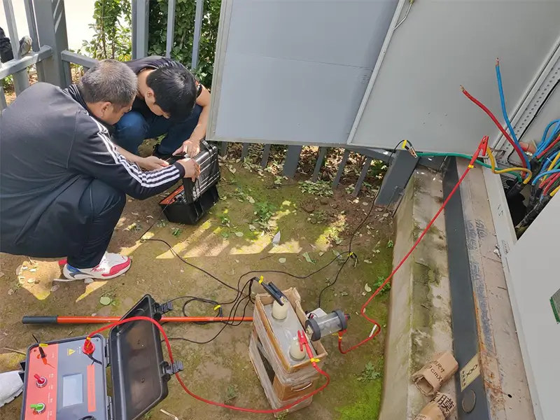
During urban underground utility upgrades, substation expansions, and emergency repairs for high-voltage power cable faults, the worst nightmare for any field foreman or safety engineer is accidentally cutting into an energized high-voltage cable.
After repair crews go through the demanding process of fault pre-location and pinpointing, they excavate the underground trench or enter the cable tunnel. There, they often face a dozen or even dozens of identical-looking, mud-covered 10kV, 35kV, or 110kV cross-linked polyethylene (XLPE) cables laid neatly side by side. At this critical moment, field operators face a vital question: Before applying hydraulic cutters or a cable saw, how can they be 100% sure that the cable in their hands is the exact target cable?
Drawing from hands-on field experience in high-voltage cable fault troubleshooting, this guide provides an in-depth analysis of live and dead cable identifiers. We will cover their underlying electromagnetic coupling principles, directional polarity judgment rules, a 5-step standard field safety operating procedure, and practical tips to avoid signal crosstalk and misjudgment.
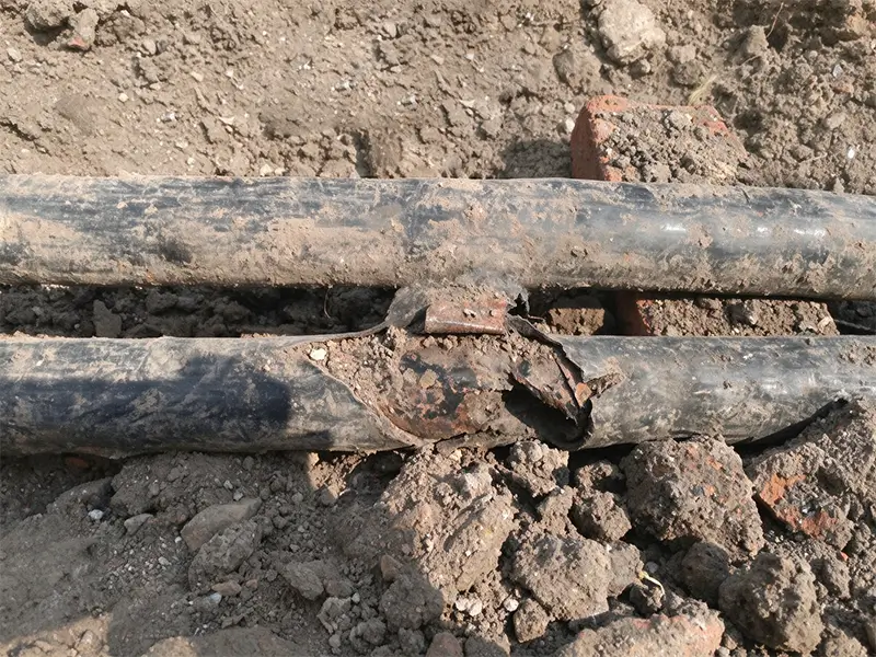
The Fatal Risks of Cable Cutting: Why “Unique Identification” Is Mandatory Before Sawing
In electrical safety regulations, positive cable identification is a mandatory red-line procedure before sawing or splicing any excavated underground cable.
Why Are Drawings, Identification Tags, and “Touch-Based Experience” Completely Unreliable in the Field?
Investigation reports of severe accidental cable-cutting incidents reveal that field crews often cause catastrophic accidents by blindly trusting three types of unreliable evidence:
1. Outdated As-Built Drawings: Over a decade or more, urban underground cable corridors undergo multiple relocations, emergency joint repairs, and conduit shifts. As a result, the vertical and horizontal arrangement of cables at manhole corners no longer matches the original as-built drawings (commonly known as “cable transposition”).
2. Missing or Misplaced Outer Sheath Tags: Cable trenches are constantly exposed to moisture, standing water, and rodent damage. Plastic identification tags easily fade, rot, and fall off—or worse, maintenance crews accidentally reattach them to the wrong cables during previous repairs.
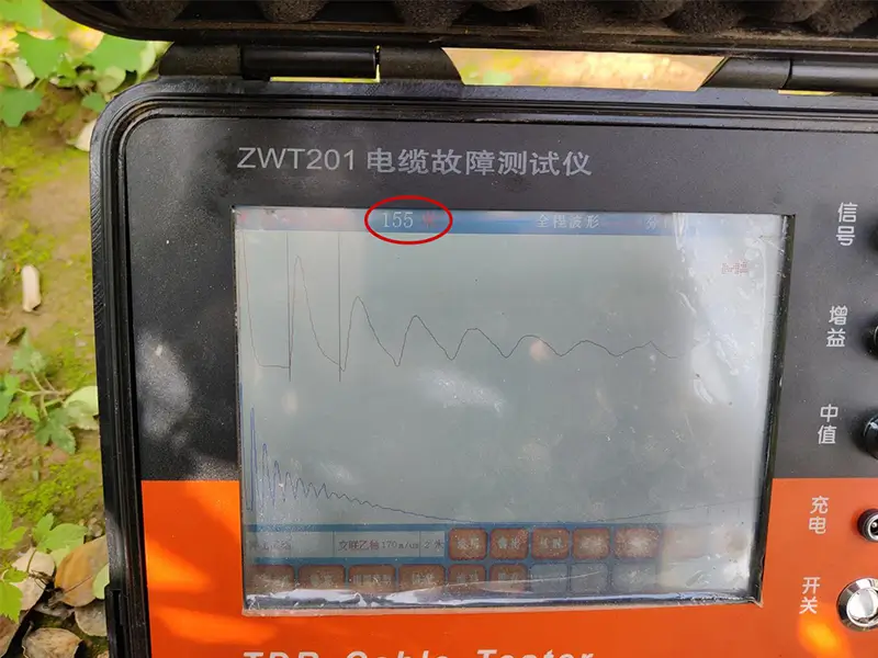
3. A Warning from a Real-World Fault Case: Consider a recent 172m single-phase-to-ground fault we handled in the field. First, technicians used the Low-Voltage Pulse (LVP) method to measure the total cable length at 172m. Next, they used an insulation resistance tester to identify the faulted phase and applied the high-voltage impulse flashover method to pre-locate the fault at 155m from the test end.
Then used a cable route tracer and an acoustic-magnetic synchronous pinpointer on the surface to pinpoint the exact fault location at the 155m mark.
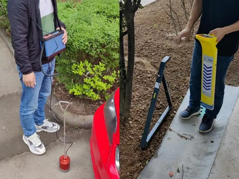
However, when the excavation crew dug open the roadbed at 155m, they found 4 armored cables of the exact same model laid tightly side by side in the trench! At this stage, the surface route tracer had finished its job. To pick out the exact target cable with the fault at 155m from those 4 tightly bundled cables, the crew had to rely on a cable identifier equipped with directional polarity discrimination.
How Does a Live Cable Identifier Work?
An industrial-grade Cable Identifier typically consists of a signal transmitter, a signal receiver, a matching transmitter clamp, and a flexible receiving current clamp. Its core physical foundation combines specific coded pulse current injection, Rogowski coil electromagnetic induction, and a dual-judgment rule based on current direction (polarity) and amplitude.
Composite Modulated Pulse-Coded Signal Injection
To avoid confusion with the power grid’s own 50Hz/60Hz power-frequency heavy currents and higher harmonics, the signal transmitter does not emit a standard continuous sine wave. Instead, it periodically injects a specially modulated, low-frequency bipolar or unipolar coded pulse current into the target cable (typically consisting of intermittent DC pulses with a specific duty cycle and a period of several seconds, or a specific composite frequency signal, with a peak current of 10A~50A).
Why Judging by “Signal Strength” Alone Leads to the Wrong Cable (The Core Logic of Directional Polarity Discrimination)
Inside a cable trench, the metallic sheaths (copper screens) and steel tape armoring of all parallel cables are bonded to the same common grounding grid at both ends of the substation. According to Kirchhoff’s Current Law (KCL):
When the transmitter injects a forward pulse current into the target cable (#1) flowing from the substation toward the remote end, that current reaches the remote ground and must return to the transmitter’s grounding terminal. It does so by flowing back through the earth and the metallic sheaths of adjacent parallel cables (#2, #3, #4) laid in the same trench, completing a closed loop!
The mathematical expression for this current conservation is:
This reveals a critical engineering phenomenon: If there are only 2 cables in a trench (1 target cable and 1 adjacent cable), the amplitude of the return current flowing through the adjacent cable will be almost identical to the forward current in the target cable! If field operators use an outdated cable locator that only indicates sound volume or signal amplitude, they face a 50% chance of cutting the wrong cable!
How Do Modern Cable Identifiers Achieve 100% Unique Identification?
Criterion 1: Current Direction (Polarity): Only the characteristic pulse current in the target cable flows out in the forward direction, whereas the return currents in all other parallel cables flow back in the reverse direction! By showing left/right pointer deflection on an analog meter or positive/negative arrows on an LCD screen, the receiver immediately rules out all cables carrying reverse current.
Criterion 2: Signal Amplitude: When multiple parallel cables (n≥3) in a trench share the return current, each adjacent cable carries only Itarget/(n−1). Consequently, the forward current amplitude in the target cable is significantly higher than that of any single return path.
Live Cable Identification vs. Dead Cable Identification
Depending on whether the target cable at the job site is energized or de-energized, cable identification operations are divided into two distinct excitation coupling modes:
Live Cable Identification Mode
When the target cable carries a critical power supply load and cannot be de-energized—or when operators at an excavation site must first identify and tag surrounding live cables for protection—a non-contact inductive coupling injection method must be used:
Connection Method: There is no need to touch any exposed high-voltage conductors. Simply clamp the transmitter’s high-permeability transmitter caliper around the main body of the cable below the cable termination in the substation (Note: It must be clamped below the trifurcating breakout and the grounding braid bonding point to ensure the metallic sheath at both ends of the cable forms a complete closed loop with the earth).
Electromagnetic Principle: The transmitter clamp acts as the primary winding of a transformer, while the closed sheath loop formed by the entire cable and the grounding grids at both ends acts as a single-turn short-circuited secondary winding. This induces a coded identification current directly onto the cable sheath.
Dead Cable Identification Mode
When the target cable has been disconnected from the grid, tested for zero voltage, and grounded due to a fault (such as the single-phase ground fault at 155m in our earlier case) or scheduled maintenance, direct connection injection is strongly recommended before cutting:
Connection Method: Clip the transmitter’s red output lead directly onto an intact copper core of the de-energized cable, and connect the black return lead to the substation’s system grounding grid. At the other end (remote end) of the cable, temporarily ground that same phase core (if a low-resistance solid ground fault has occurred, the fault point itself can form the return loop, though reliable manual grounding at the remote end yields the best results).
Core Advantage: Because the coded pulse current flows directly through the highly conductive main cable core, it is completely unaffected by poor outer sheath grounding. This delivers an exceptionally high signal-to-noise ratio (SNR) and extends the effective identification distance to 10km~30km.
Technical Parameter Comparison: Live Mode vs. Dead Mode
| Comparison Dimension | Live Identification Mode | Dead Direct-Connection Identification Mode |
|---|---|---|
| Target Cable Status | Energized and operating (or de-energized where disconnecting terminations at both ends is impractical) | Completely de-energized, isolated, tested for zero voltage, and grounded |
| Signal Injection Method | Inductive coupling injection via transmitter clamp (non-contact, safe, and fast) | Direct injection by clipping red and black alligator clips onto the exposed conductor core |
| Signal Flow Path | Cable metallic screen / steel tape armor → Grounding grid loop at both ends | Main cable conductor core → Remote grounding lead → Earth return loop |
| Prerequisite Loop Condition | Metallic sheath must be properly grounded at both ends to form a closed loop | Tested phase core must be grounded at the remote end (forming a conductive path) |
| Effective Identification Distance | Short to medium distance (typically ≤2km~5km, limited by sheath impedance) | Ultra-long distance (up to 10km~30km or more) |
| Typical Engineering Purpose | Corridor surveys, live cable tagging, confirming surrounding live cables before excavation | Final confirmation of the de-energized target cable right before cutting |
5-Step Standard Field Safety Operating Procedure
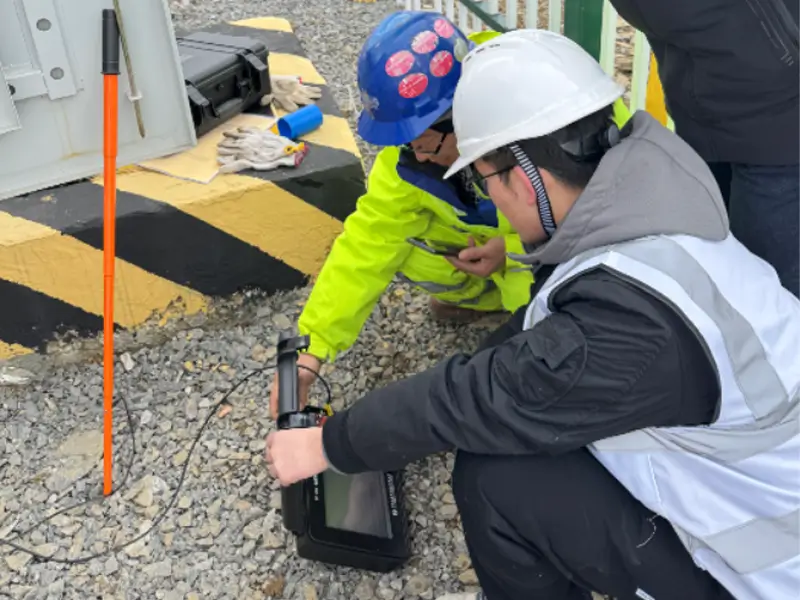
Step 1: Apply the Characteristic Signal to the Target Cable at the Substation End
For de-energized cable cutting operations, first verify the substation switchgear panel number. After testing the cable to confirm it is de-energized, disconnect one intact phase core of the target cable from the grounding busbar and clip the transmitter’s red output lead to it. Attach the black return clip to the substation’s main grounding flat bar, and reliably ground that same phase core at the remote end of the cable. Turn on the transmitter and check the output ammeter for a steady pulse deflection.
Step 2: Perform “Polarity and Sensitivity Reference Calibration” at the Transmitter End (Extremely Critical!)
Before heading to the excavation trench, perform a baseline calibration on the target cable at the transmitter output using the flexible current clamp (Rogowski coil):
Check the directional arrow on the clamp’s latch to ensure it points toward the remote end of the cable (away from the transmitter). Turn on the receiver and adjust the gain knob (or press the auto-calibrate button) until the analog needle settles at full-scale deflection in the positive zone to the right (+ polarity), or the digital display shows a forward arrow (▲) and a reference level of 0 dB.
Step 3: Clamp Around Each Parallel Cable One by One at the Excavation Site
Upon arriving at the excavation site (such as the fault pit dug at 155m in our earlier case), wrap the flexible receiving current clamp around each parallel cable in the trench one at a time.
When clamping around every cable in the trench, the directional arrow on the flexible receiving clamp must match the exact direction used during the Step 2 calibration (always pointing toward the remote end / load end of the cable)! If you clamp the coil backward, the positive and negative polarities will be completely reversed! For each measurement, ensure the flexible coil clasp is fully closed and locked, and enclose only one cable at a time.
Step 4: Observe the Receiver Meter and Execute the “Direction + Amplitude” Dual Judgment
After testing all cables in the trench one by one (assuming 4 cables) and recording the readings, compare the test results:
| Cable No. in Trench | Pulse Polarity (Direction) Detected by Receiver | Receiver Signal Amplitude Ratio | Comprehensive Judgment Result |
|---|---|---|---|
| Cable #1 | Forward deflection (+ / Green right deflection) | 92% (Strongest) | [√] 100% Locked as Target Cable |
| Cable #2 | Reverse deflection (- / Red left deflection) | 35% (Weaker) | [×] Non-target (Return current adjacent cable) |
| Cable #3 | Reverse deflection (- / Red left deflection) | 30% (Weaker) | [×] Non-target (Return current adjacent cable) |
| Cable #4 | No noticeable pulse deflection | <2% | [×] Non-target (Cable from a different route) |
Sole Passing Criterion: There must be one—and only one—cable in the trench that exhibits both forward deflection (+) and the highest amplitude. If two cables display positive polarity at the same time, or if all cables show weak signals with chaotic polarity, cutting is strictly prohibited! You must return to the substation to inspect the grounding loop and wiring connections.
Step 5: The Ultimate Physical Defense Before Cutting: Safe Cable Spiker Interlock
Even after electronic identification is complete, international and national electrical safety regulations mandate one final physical fail-safe before severing high-risk, high-voltage cables: using a cartridge-actuated or hydraulic remote-controlled cable spiker:
1. Secure the cable spiker onto the identified target cable at the exact point where the cut will be made;
2. Evacuate all construction personnel from the cable trench to a safe shelter on the surface 15m~30m away;
3. The operator triggers the spiker using a wireless remote control or a long-distance insulated lanyard, driving a high-strength alloy steel spike instantaneously through the cable sheath and three-phase cores (creating an intentional, direct metallic short-circuit to ground);
4. Only after confirming there is no arc blast at the spiking point and no abnormal circuit breaker tripping sounds may field personnel re-enter the trench and safely cut the cable right next to the puncture hole!
Common Field Misconceptions and Pitfall Avoidance Guide
In actual engineering practice, ignoring the metallic screen grounding structure of a cable can easily lead operators into two major technical traps:
Trap 1: Clamping the Transmitter Caliper in the Wrong Position, Resulting in “Zero Net Current (Magnetic Flux Cancellation)”
When using inductive coupling on a live cable or clamping a transmitter caliper around a three-core belted cable, the most common mistake is placing the clamp above the grounding copper braid at the cable termination (enclosing both the three-phase cores and the downward-leading grounding copper braid at the same time).
Correct Practice: The transmitter clamp must be positioned on the main cable body below the bifurcation point of the termination’s grounding copper braid (or ensure the grounding copper braid is routed around the outside of the clamp). Only then can the induced current flow along the armor/screen layer toward the remote earth.
Trap 2: Sheath Circulating Current Interference in Single-Point Grounded or Cross-Bonded Cables
For 110kV and above single-core high-voltage cables, utilities suppress power-frequency induced circulating currents by grounding one end directly while grounding the other end through a Sheath Voltage Limiter (SVL), or by using a three-section cross-bonded grounding arrangement.
How to Avoid This Trap: On a single-point grounded live cable, the remote sheath is effectively open-circuited (since the SVL does not conduct under low voltage). As a result, a live transmitter clamp cannot induce a closed-loop current in the sheath! If identification is required under these conditions, the cable must be de-energized so the remote sheath voltage limiter can be temporarily shorted to ground, or operators must switch to the dead direct-connection method and inject the signal directly into the main conductor core.
EXPERT GUIDANCE
Need Help Choosing the Right Testing Equipment?
Frequently Asked Questions (FAQ)
Q1: Can a live cable identifier work properly on cables with heavy steel tape armoring and copper screen layers?
Absolutely. This applies to both dead and live modes: In dead direct-connection mode, the coded pulse current flows from the internal copper core toward the remote end. As long as the return current flows back through the earth or adjacent cables (rather than returning entirely through the target cable’s own screen layer), the flexible receiving clamp can clearly detect the net magnetic field generated by the core from outside the armor.
To ensure this, always disconnect the target cable’s copper screen grounding braid from the tested core at the transmitter end during testing (do not let the signal return directly through the cable’s own screen layer). In live inductive coupling mode, the coded signal naturally flows directly along the steel tape armor and copper screen layer, giving the external flexible current clamp exceptionally high detection sensitivity.
Q2: What is the fundamental difference between a cable route tracer and a cable identifier?
As demonstrated in our earlier 172m cable fault field case, the two instruments serve completely different yet complementary roles:
Cable Route Tracer: Used above ground before excavation to trace the underground cable’s routing path, turning corners, and burial depth (such as locating the exact spot on the concrete pavement directly above the 155m fault point). Because its receiving probe uses an open induction coil, it cannot distinguish between multiple cables laid tightly side by side inside a trench.
Cable Identifier: Used after excavating the trench or entering a tunnel, when operators face an exposed bundle of parallel cables. Using a closed-loop flexible Rogowski coil clamped around each cable individually, it compares current direction (positive/negative polarity) and amplitude to pick out the single target cable from multiple cables with 100% accuracy. Never use a surface route tracer in place of a cable identifier to guide cable cutting!
Q3: Why is the arrow direction on the flexible receiving current clamp so important?
A flexible receiving current clamp (Rogowski coil) has a strict electromagnetic winding polarity. The receiver determines whether the current is “flowing toward the remote end (+)” or “returning to the near end (-)” by comparing the phase relationship between the transmitted pulse and the electromotive force induced in the receiving coil.
If an operator randomly flips the coil orientation while testing different cables in the trench, a non-target cable carrying reverse return current will falsely display as positive (+), leading to a catastrophic misjudgment. Therefore, field crews must always follow this rule of thumb: “Keep the arrow pointing toward the remote end; the strongest positive deflection is your target.”
Conclusion and Complete Equipment Selection
In high-voltage power cable maintenance and emergency repair operations, cable identification is far more than a routine testing step—it is the final safety barrier protecting field personnel lives and preventing widespread accidental grid blackouts.
To recap, achieving a 100% accurate lock on the target cable before cutting requires field teams to rely on two core elements: First, strictly following standardized field safety operating procedures (including reference calibration and physical safe cable spiking); second, equipping the crew with an industrial-grade cable identifier that features true dual-judgment capabilities for both “current directional polarity” and “signal amplitude.”
Under complex field conditions where multiple cables are laid tightly side by side, relying solely on drawing tags or outdated signal-strength line locators is extremely dangerous.
Furthermore, in real-world engineering projects, cable identification is just one link in the overall fault troubleshooting workflow. A complete underground cable O&M and emergency repair solution typically requires the coordinated deployment of a cable fault pre-location system, an underground utility route locator, an acoustic-magnetic synchronous pinpointer, a live/dead cable identifier, and a remote-controlled safe cable spiker.
EXPERT GUIDANCE
Need Help Choosing the Right Testing Equipment?
Need to Match the Right Cable Testing Equipment for Your Engineering Project?
Power grid architectures, cable installation methods (such as direct burial, conduit banks, or tunnels), and sheath grounding standards vary widely across different countries and regions. A single off-the-shelf device often cannot handle every complex field challenge.
As a professional power testing equipment manufacturer and solution provider, we supply not only high-precision live/dead dual-mode cable identifiers, but also fully customized, end-to-end cable fault location and safety identification solutions tailored to your specific field conditions.
Contact our engineering team today for dedicated support:
Free Technical Consultation & Custom Solutions: Tell us the cable voltage levels you commonly handle (such as 10kV, 35kV, 110kV and above), your installation environments, and your testing requirements. Our engineers will prepare a targeted equipment selection list and technical proposal for you within 24 hours.
Get Product Brochures & Quotes: Request detailed technical datasheets and factory quotes for our latest cable identifiers and complete cable fault test systems.
OEM / ODM & Custom Specifications: We support customization of transmitter power, flexible Rogowski coil sizes (to fit ultra-large diameter cables), user interface languages, and local grid frequency adaptations based on your project requirements.
Click Here to contact us, or email us directly at sales001@zhiweielectric.com, and let our technical experts help your team achieve safe and efficient field operations every time!