
Throughout the manufacturing and operational lifecycle of high-voltage (HV) electrical assets, conventional power-frequency withstand voltage testing is primarily used to verify the instantaneous dielectric strength of the insulation system (i.e., whether disruptive breakdown occurs).
In contrast, partial discharge measurement (PD testing) quantitatively detects minute localized electrical discharge activity within the insulation long before breakdown occurs. This allows engineers to evaluate the degree of insulation degradation and predict the asset’s long-term operational reliability.
Even if an HV asset passes factory withstand testing without dielectric breakdown, micro-voids, impurities, or metallic burrs within the insulation may still harbor partial discharges. Over time, continuous PD activity accelerates insulation aging, eventually triggering catastrophic equipment failure.
Serving as the globally recognized benchmark, IEC 60270 strictly standardizes PD measurement principles and metrological traceability. This article delivers an in-depth breakdown of the standard’s core definitions, four recommended test circuits, pulse charge calibration procedures, and allowable PD limits across major power apparatus.
What is the IEC 60270 Standard? Scope and Engineering Objectives
The full title of IEC 60270 is “High-voltage test techniques – Partial discharge measurements.” Published by the International Electrotechnical Commission (IEC), it serves as the foundational reference for quantitatively measuring partial discharge in electrical apparatus under alternating voltage (up to 400 Hz) or direct voltage stress using the pulse current method. According to the official IEC 60270 definition, partial discharge is: “A localized electrical discharge that only partially bridges the insulation between conductors and which can or cannot occur adjacent to a conductor.”
Applicable Core Electrical Assets
IEC 60270 specifies universal measurement principles and instrumentation guidelines, which are widely applied during factory acceptance testing (FAT) and on-site commissioning of the following high-voltage assets:
Large Power Transformers and Shunt Reactors: Evaluating oil-paper barrier systems, inter-turn/inter-winding insulation, and HV lead insulation.
Instrument Transformers (CT / PT / CVT): Assessing solid epoxy cast resin or oil-paper insulation systems in inductive and capacitive transformers.
Medium- and High-Voltage Switchgear and GIS: Gas-insulated metal-enclosed switchgear (SF6 GIS), circuit breakers, wall bushings, and post insulators.
Power Cables and Accessories: High-voltage cross-linked polyethylene (XLPE) cable bodies, intermediate joints, and terminations.
High-Voltage Bushings and Power Capacitors: Evaluating condenser core foil edges and composite oil/resin interfaces.
Large Rotating Machines: Assessing the mica-based groundwall and turn insulation of HV generators and motors.
Core Technical Terms Defined by IEC 60270
When reviewing test reports or conducting PD tests, test engineers must master the following five core physical parameters defined by IEC 60270:
1. Apparent Charge (q, in pC)
This is the most critical parameter in IEC 60270. Because the actual discharge site is buried deep within the insulating material, it is physically impossible to place a probe inside the microscopic void to measure the true local charge displacement.
Standard Definition: The apparent charge q is that charge which, if injected instantaneously between the terminals of the test object, would produce the same transient voltage change across its terminals as the partial discharge itself.
Unit of Measure: Picocoulomb (pC), where 1 pC = 10⁻¹²C.
2. Partial Discharge Inception Voltage (PDIV)
The lowest RMS test voltage at which repetitive PD pulse signals are first observed on the measurement instrument (exceeding a specified background noise threshold) as the applied voltage is gradually increased from a low, discharge-free level.
3. Partial Discharge Extinction Voltage (PDEV)
The RMS test voltage at which repetitive PD pulses completely cease (drop below the specified threshold) as the applied voltage is gradually reduced from a level higher than the PDIV.
Engineering Rule of Thumb: Due to space charges left by preceding discharges and gas ionization hysteresis, the extinction voltage (PDEV) is typically lower than the inception voltage (PDIV)—generally around 70% to 85% of PDIV. If an asset’s nominal operating phase-to-ground voltage is higher than its PDEV, a temporary network overvoltage can ignite PD activity that will continue burning indefinitely even after voltage returns to normal!
4. Pulse Repetition Rate (n)
The ratio of the total number of PD pulses recorded within a chosen, equidistant time interval to the duration of that interval (i.e., the average number of discharge pulses occurring per second). It reflects the density and intensity of the internal insulation defect.
5. Background Noise Level
The amplitude of interference signals (expressed in pC) displayed by the measuring system before high voltage is applied or in the absence of PD within the test object. IEC 60270 requires the background noise level to remain below 50% of the allowable PD limit for the test object (ideally below 20% to 30%).
IEC 60270 Standard PD Measurement Circuit Setup (Four Core Components)
According to IEC 60270 test circuit guidelines, a standard parallel-method pulse current PD measurement setup (coupling capacitor connected in series with the measuring impedance) consists of four primary hardware components alongside the acqu isition instrument:
1. PD-Free High-Voltage Test Power Source
Conventional high-voltage test transformers exhibit significant inherent electromagnetic noise and baseline partial discharges, which easily obscure the delicate picocoulomb-level signals of the test specimen. Consequently, an IEC 60270 test setup requires a low-noise, PD-free power source (typically rated at < 1 pC ~ 5 pC background discharge).
Selection Note: As outlined in our guide “Dry-Type vs. Oil-Immersed vs. SF6 Gas-Insulated Test Transformer Selection Guide,” conventional epoxy-cast dry-type test transformers typically exhibit background PD levels of 20 pC~50 pC, rendering them unsuitable for precision PD measurements. In engineering practice, it is imperative to use insulating-cylinder oil-immersed test transformers, SF6 gas-insulated PD-free test transformers, or variable-frequency PD-free series resonant test systems.
2. High-Voltage Filter / Blocking Impedance (Z)
Connected in series between the high-voltage source and the measurement circuit (typically an inductive choke). It serves two essential purposes:
Attenuating Mains-Borne HF Interference: Prevents high-frequency grid harmonics, voltage regulator switching noise, and step-up transformer disturbances from penetrating the downstream PD measurement circuit.
Preventing High-Frequency Pulse Shunting: Prevents the nanosecond-level PD current pulses generated by the test object from leaking back into the power source, ensuring the pulse current is directed predominantly through the coupling capacitor (Ck).
3. Test Object (Ca) and Coupling Capacitor (Ck)
During a high-frequency partial discharge event, the test object behaves essentially as a lumped capacitance Ca. When a discharge occurs within Ca, its terminal voltage experiences a minute, instantaneous drop ΔVa. In that instant, the parallel PD-free coupling capacitor (Ck), acting as a low-impedance path at high frequencies, immediately discharges a transient compensation pulse current i(t) into Ca. This establishes a high-frequency loop current across the Ca–Ck–Zm closed network that can be detected.
To maximize measurement sensitivity (i.e., capturing the greatest proportion of charge transfer), the capacitance of Ck should be larger than or at least comparable to that of Ca. The actual captured charge qm, determined by the capacitive divider relationship of the circuit, is given by:
When Ck ≫ Ca, the measured charge qm approaches the actual apparent charge q. In field and factory applications, PD-free standard coupling capacitors ranging from 500 pF~2000 pF are standard.
4. Measuring Impedance / Coupling Device (Zm or CD)
Also known as an input unit or four-terminal network, Zm is typically connected in series with the low-voltage ground terminal of the coupling capacitor Ck (if the test object’s low-voltage terminal is isolated from ground and has low capacitance, it can be connected below Ca to maximize sensitivity).
Core Function: Converts the high-frequency transient current pulses flowing through Ck into proportional voltage pulses, safely routes high 50 Hz/60 Hz power-frequency currents directly to ground, and transmits the filtered high-frequency PD signals to the PD detector via a double-shielded coaxial cable.
5. Instrument Bandwidth Specified by IEC 60270 (Wideband vs. Narrowband)
IEC 60270 strictly classifies the bandpass filtering parameters of PD acquisition systems into two categories:
| Measurement System Type | Lower Cut-off Frequency (f₁) | Upper Cut-off Frequency (f₂) | Equivalent Bandwidth (Δf = f₂ − f₁) | Engineering Characteristics & Application |
|---|---|---|---|---|
| Wideband PD System | 30 kHz ≤ f₁ ≤ 100 kHz | f₂ ≤ 500 kHz (or extended up to 1 MHz) | 100 kHz ≤ Δf ≤ 400 kHz (or up to 900 kHz) | Features exceptional pulse resolution with short response times and minimal pulse overlap. Accurately preserves positive and negative polarity, making it the standard architecture in modern digital PD analyzers. |
| Narrowband PD System | Center frequency fₘ tunable between 50 kHz ~ 1 MHz | f₂ = fₘ + Δf/2 | 9 kHz ≤ Δf ≤ 30 kHz | Very narrow bandwidth allows tuning out continuous carrier communications or localized radio broadcast frequencies. However, longer pulse ringing limits positive/negative polarity discrimination. |
PD Calibrator and Pulse Calibration Procedure (IEC 60270)
Why must an on-site calibration be executed within the active test circuit prior to every high-voltage PD test?
Because the equivalent capacitance Ca of each test object, the stray capacitance of high-voltage leads to ground, and the circuit impedances vary in every single test setup. The same 10 pC internal discharge will produce pulse voltage amplitudes across the measuring impedance Zm that differ by a factor of 10 or more when testing a small CT (Ca = 200 pF) versus a large power transformer (Ca = 8000 pF)! Without in-situ calibration, the readings on the instrument screen carry zero physical significance.
Standard Pulse Injection Method: Four-Step Procedure
Step 1: Principles of the Calibration Pulse Generator
A standard PD calibrator consists of a precision step-voltage generator outputting a step voltage U0 connected in series with a high-precision calibration capacitor C0. Based on the fundamental charge equation, the reference charge q0 injected into the circuit on each voltage step is:
IEC 60270 strictly mandates that to prevent the calibrator itself from causing capacitive loading errors, C0 must satisfy C0 ≤ 0.1 × Ca (standard calibrators typically use C0 = 50 pF or 100 pF, with a step rise time tr ≤ 60 ns).
Step 2: Connecting Across the De-Energized Test Object
With the complete test circuit fully assembled but strictly de-energized, connect the output leads of the portable, battery-powered pulse calibrator directly across the high-voltage and ground terminals of the test object Ca. (Note: Keep calibration leads as short as possible to minimize loop inductance).
Step 3: Injecting Known Charge and Locking the Scale Factor
Set the calibrator’s output level close to the target acceptance threshold of the test specimen (e.g., if the limit is ≤ 10 pC, inject 5 pC, 10 pC, or 20 pC; if evaluating a transformer with a limit of ≤ 100 pC, inject 50 pC or 100 pC).
Switch on the calibrator. Stable calibration pulses will appear on the ellipse or sine-wave display of the PD measurement system. Enter the nominal injected charge value (e.g., 50 pC) into the software interface and click “Confirm Calibration.” The system will automatically compute and lock the circuit’s scale factor (k).
Step 4: Disconnecting the Calibrator (Strict Safety Protocol)
【Critical Safety Warning】 Once calibration is locked, the pulse calibrator must be completely disconnected from the high-voltage terminals and removed from the test perimeter before applying high voltage! Leaving the calibrator connected when high voltage is energized will instantly destroy the instrument and trigger severe flashovers or short circuits.
Acceptance Criteria: How Many pC Are Allowed?
Engineers consulting the standard for the first time often ask: “Why are there no specific pass/fail pC limits for transformers or switchgear inside IEC 60270?” This is because IEC 60270 is a methodology standard; it defines how to measure 1 pC accurately. The actual pass/fail discharge limits are governed by the dedicated product standards for each specific asset class.
To assist QA and testing engineers, the table below consolidates the allowable PD limits across major electrical apparatus under the latest IEC and national standards:
Quick Reference: PD Acceptance Limits for Major HV Assets:
| Equipment Category | Governing Standard | Test Voltage Level (Measurement Point) | Maximum Permissible Apparent Charge (qₘₐₓ) | Engineering Notes |
|---|---|---|---|---|
| Liquid-Immersed Power Transformers | IEC 60076-3 | 1.58Uᵣ / √3 (1-hour long-duration induced withstand, ACLD) | ≤ 100 pC ~ 250 pC (Short-duration ACSD typically requires ≤ 300 pC ~ 500 pC) | Stringent tender specifications for modern EHV/UHV units frequently mandate ≤ 100 pC under ACLD with no rising trend over time. |
| Dry-Type Power Transformers | IEC 60076-11 | 1.3Uᵣ (pre-stressed at 1.8Uᵣ for 30 s, reduced to 1.3Uᵣ for 3 min) | ≤ 10 pC | Discharges exceeding 10 pC in cast-resin windings rapidly accelerate electrical treeing and thermal cracking. |
| Instrument Transformers (CT / PT) | IEC 61869-1 | 1.2Uₘ or 1.2Uₘ / √3 (depending on system grounding) | Liquid-immersed: ≤ 5 pC or 10 pC; Solid cast resin: ≤ 20 pC or 50 pC | At the 1.2Uₘ / √3 test point, oil-immersed units must strictly not exceed 5 pC; solid insulation must not exceed 20 pC. |
| Gas-Insulated Switchgear (SF₆ GIS) | IEC 62271-203 | 1.2Uᵣ / √3 (measured following pre-stress withstand test) | ≤ 5 pC (factory internal quality limits often enforce ≤ 2 pC ~ 3 pC) | SF₆ gas is extremely sensitive to free conductive particles; discharges over 5 pC from sharp protrusions or floating potentials rapidly trigger dielectric flashover. |
| MV XLPE Power Cables (6 kV to 30 kV) | IEC 60502-2 | 1.73U₀ (pre-stressed at 2.0U₀ for 10 s, reduced to 1.73U₀) | ≤ 10 pC (high-grade factory benchmarks often target ≤ 5 pC) | Verifies the absence of micro-voids and protrusions at the interfaces between the XLPE insulation and semiconductive screens. |
| HV XLPE Power Cables (36 kV to 500 kV) | IEC 60840 / IEC 62067 | 1.5U₀ or 1.73U₀ | ≤ 5 pC (or no detectable discharge above baseline noise) | Factory acceptance tests for EHV cables demand zero detectable discharge activity at an instrument sensitivity of ≤ 2 pC ~ 5 pC. |
| HV Wall Bushings & Transformer Bushings | IEC 60137 | 1.05Uₘ / √3 and 1.5Uₘ / √3 | At 1.05Uₘ / √3: ≤ 5 pC; At 1.5Uₘ / √3: ≤ 10 pC | Evaluates the manufacturing quality between condenser core foil layers in oil-impregnated paper (OIP) or resin-impregnated paper (RIP) designs. |
Noise Suppression Challenges and PRPD Diagnosis in Field Testing
Inside a dedicated factory testing bay shielded by a six-sided Faraday cage, background noise is easily held below 1 pC. However, when engineers deploy testing equipment to an active substation for on-site commissioning, ambient electromagnetic interference (EMI) often introduces dozens or even hundreds of picocoulombs of noise, overwhelming the specimen’s real signals.
1. Three Typical Field Noise Sources
Radiated Air Corona: Spatial corona generated by the sharp points of adjacent energized busbars or overhead transmission lines, which couples directly into the test loop via high-voltage connecting leads.
Conducted Power-Line Interference: High-frequency noise from variable frequency drives (VFDs), welding equipment, thyristor switching harmonics, and transient pulses riding on temporary site distribution supplies.
Ground Loop Circulating Currents: High-frequency stray currents circulating through the substation grounding grid that enter the measurement impedance via ground potential differences caused by multi-point grounding.
2. Modern Anti-Interference Techniques Complying with IEC 60270
To suppress background noise without attenuating genuine discharge pulses, modern digital PD analyzers utilize several core techniques (all approved under IEC 60270 Annexes):
Digitally Tunable Bandpass Filtering: Using real-time Fast Fourier Transform (FFT) analysis to flexibly adjust the lower cutoff f1 and upper cutoff f2, steering the measurement window away from dense fixed-frequency carrier interference bands.
Phase Windowing and Dynamic Time-Gating: When external noise is phase-locked to specific angles of the power-frequency cycle (such as thyristor firing spikes), phase windows can blank out those segments. Alternatively, an external RF antenna channel can capture ambient interference pulses and trigger a microsecond-level hardware gate that closes the measurement channel when noise arrives.
Balanced Bridge Circuitry: Utilizing two symmetrical measuring impedances (connected beneath the test specimen Ca and coupling capacitor Ck , respectively) and a differential amplifier to cancel common-mode external interference while extracting the specimen’s differential-mode PD signals.
3. PRPD Phase-Resolved Patterns: Distinguishing Internal PD from External Corona
Experienced engineers do not rely solely on absolute pC magnitudes; they evaluate Phase-Resolved Partial Discharge (PRPD) patterns to identify the specific defect mechanism:
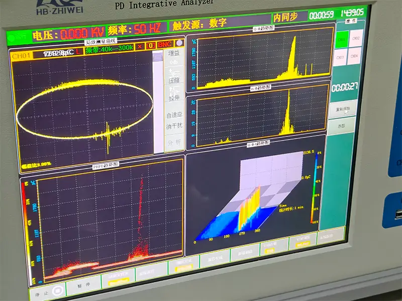
Internal Void Discharge (Solid/Liquid Insulation): Pulses cluster symmetrically along the rising voltage slopes in the 1st quadrant (0° ~ 90°) and 3rd quadrant (180° t~ 270°) of the power sine wave. This indicates an internal dielectric cavity—the most hazardous insulation defect.
External High-Voltage Corona Discharge: Pulses cluster tightly around the negative voltage peak (around 270°), with virtually no activity on the positive half-cycle. Observing this pattern indicates the test object itself is intact; adding a larger anti-corona shielding sphere or grading ring to the high-voltage connection will instantly eliminate the noise reading.
Floating Potential Discharge: Caused by ungrounded or loose internal metallic hardware. It produces a characteristic “picket fence” pattern featuring identical pulse amplitudes, high repetition rates, and near-perfect symmetry across both positive and negative half-cycles.
Frequently Asked Questions (FAQ)
Q1: Why does IEC 60270 measure “apparent charge” rather than “real charge”?
Partial discharges occur within microscopic voids or defects buried inside the dielectric. When a localized breakdown happens inside a void, the true physical charge transferred cannot be directly detected at the external terminals due to complex capacitive voltage-divider attenuation between the void and surrounding bulk insulation. Furthermore, the void’s geometry, depth, and dielectric parameters are inherently unknown.
To overcome this, IEC 60270 establishes the equivalent concept of “apparent charge” (q, in pC): the charge that, if injected across the external terminals, creates a transient voltage change identical to that caused by the internal event. This equivalence allows discharge activity across diverse assets and test setups to be standardized, calibrated, and directly compared using reference pulse calibrators.
Q2: Can online screening methods like UHF, Acoustic Emission (AE), or TEV produce a legally valid IEC 60270 test certificate?
No, they cannot serve as a direct equivalent. Ultra-High Frequency (UHF), Acoustic Emission (AE), Transient Earth Voltage (TEV), and High-Frequency Current Transformers (HFCT) are non-conventional PD diagnostic methods (governed by IEC TS 62478).
Because electromagnetic and acoustic wave propagation paths inside complex apparatus suffer unpredictable attenuation and scattering, these methods cannot achieve absolute calibration in picocoulombs (readings are typically expressed in mV or dBm). They are invaluable tools for online troubleshooting and defect localization on operating equipment. However, for Factory Acceptance Testing (FAT) and formal commercial commissioning, the IEC 60270 pulse current method remains the sole legally binding standard for contractual pass/fail determination.
Q3: How do you build a truly “PD-free” test loop in an on-site testing environment?
To keep the baseline discharge of the entire high-voltage test loop below 2 pC to 5 pC, three technical conditions must be satisfied:
1) Use Low-Noise Test Equipment: Deploy a power source with verified low baseline discharge (such as an SF6 gas-insulated transformer or insulating-cylinder oil-immersed transformer) paired with a low-loss, PD-free coupling capacitor.
2) Use High-Voltage Shielded Leads: Replace thin bare copper wire with large-diameter corrugated aluminum tubing or flexible braided HV shielding conduit to prevent conductor surface ionization.
3) Install Corona Shields: Fit polished aluminum grading rings or corona spheres onto all high-voltage terminals, dividers, and coupling capacitor tops to eliminate local field intensification and prevent air corona.
Conclusion
Executing partial discharge testing in strict compliance with IEC 60270 is a critical defense line for validating the long-term integrity of high-voltage insulation systems. A successful PD test involves far more than simply reading a number off an instrument; it requires a disciplined, compliant test ecosystem. This includes utilizing a low-noise PD-free power source, selecting a properly matched coupling capacitor, performing rigorous in-situ pulse calibration prior to energization, and applying PRPD pattern analysis to isolate external noise.
By establishing standardized measurement circuits and accurate quantitative analysis, manufacturers and testing laboratories can identify microscopic insulation flaws long before irreversible breakdown occurs, ensuring high-voltage assets operate reliably once connected to the grid.
Configure Your IEC 60270 Partial Discharge Test System
As a dedicated manufacturer of high-voltage test systems and PD diagnostics, HB ZHIWEI provides robust, reliable testing solutions tailored for Factory Acceptance Testing (FAT), site commissioning, and routine preventive maintenance:
PD-Free High-Voltage Power Supply Systems: We supply a comprehensive range of high-voltage test transformers, including ultra-low PD insulating-cylinder oil-immersed units and SF₆ gas-insulated test transformers, as well as variable-frequency PD-free series resonant test systems engineered for high-capacitance test loads (such as long cables, GIS, and large generators);
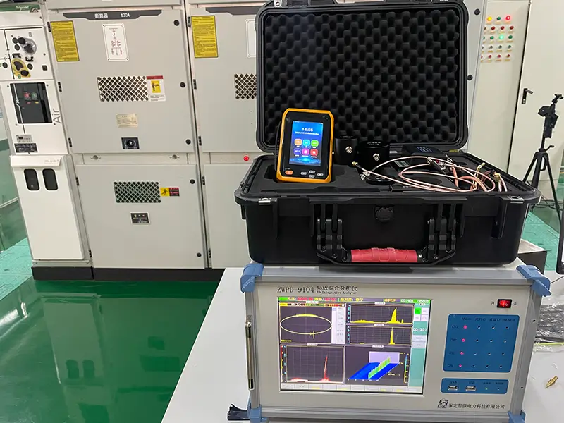
Laboratory-Grade Benchtop PD Analyzers: Fully compliant with IEC 60270, our systems feature precision measuring impedances, standard coupling capacitors, and pulse calibrators, supporting multi-channel synchronous acquisition and PRPD phase pattern diagnostics.
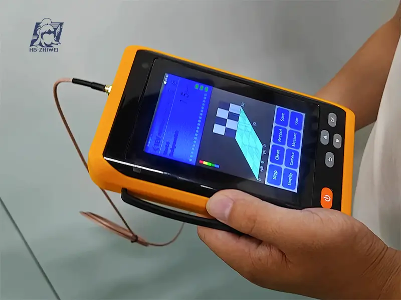
Handheld PD Diagnostic Instruments: Engineered for rapid on-site screening and substation condition assessment, integrating multi-sensor technologies including UHF, Acoustic Emission (AE), and TEV.
Need assistance sizing a PD detection system or high-voltage test source for your specific test objects? Contact our engineering team today to receive complete technical specifications, application wiring schematics, and an official quote.