
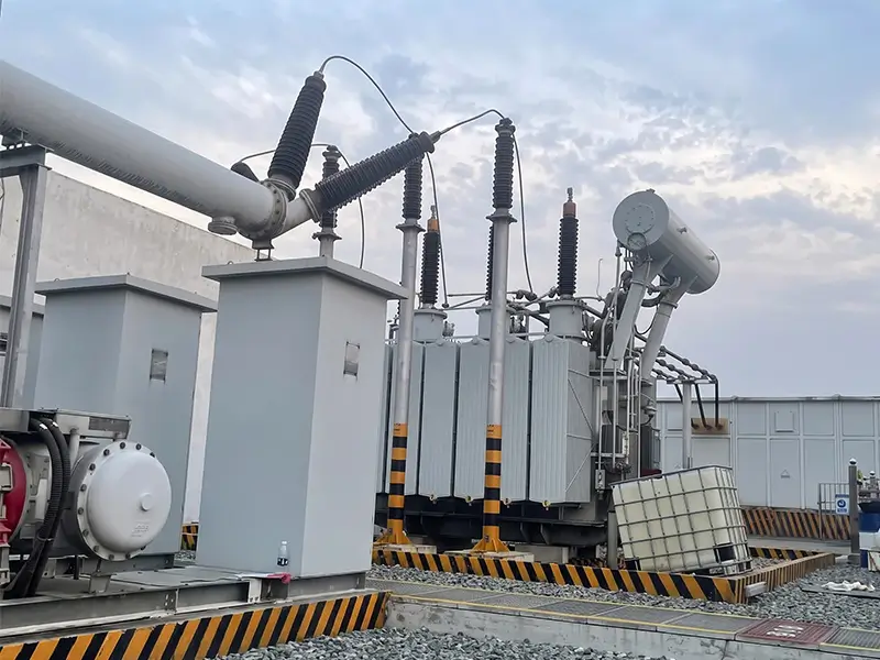
In power generation plants, substation commissioning acceptance, and preventive maintenance of electrical apparatus, the power-frequency AC withstand voltage test (AC Hipot test) is the definitive method for verifying main insulation dielectric strength.
Within the test loop, the high-voltage testing transformer (commonly known as a Hipot transformer, step-up transformer, or pressure booster) serves as the core source providing a continuously adjustable reference high voltage. However, when procurement engineers and field test supervisors select a testing transformer, they face a critical dilemma: between dry-type, oil-immersed, and SF6 gas-insulated designs, which one is the right choice?
While all three types share the same electromagnetic induction operating principle, their internal insulating and cooling media—vacuum-cast epoxy resin, high-voltage mineral insulating oil, and high-purity sulfur hexafluoride (SF6) gas—differ vastly in physical and chemical characteristics. These media dictate substantial differences in unit weight, portability, maximum voltage rating, partial discharge (PD) performance, environmental resilience, and long-term maintenance costs.
Based on the international IEC 60060 standard, this guide provides an in-depth breakdown of the technical strengths, operational trade-offs, and engineering selection logic for each of the three major testing transformer types.
Table of Contents
Testing Transformer Overview and the Core Role of Insulating Media
A power-frequency withstand test is fundamentally a destructive dielectric test: by applying an electrical stress significantly higher than the rated operating voltage to the device under test (DUT)—such as power cables, circuit breakers, power transformers, and surge arresters—it stresses insulation margins to expose latent defects.
Inside the testing transformer, the insulating medium isolates the high-voltage winding from the low-voltage winding, the windings from the iron core, and the assembly from the grounded outer enclosure. Crucially, it also governs thermal dissipation, operating temperature rise, and corona resistance:
Solid Medium (Epoxy Resin): Mechanically rigid and compact; completely eliminates liquid and gas leakage risks, though electric field uniformity within the casting is comparatively limited.
Liquid Medium (Transformer Oil): High dielectric constant with natural convective heat dissipation and self-healing dielectric properties; excels at absorbing transient high-voltage surges, but adds significant overall weight.
Gas Medium (SF6): Exceptional electronegativity (readily captures free electrons to form stable negative ions) combined with outstanding arc-quenching capabilities. Its dielectric strength is approximately 2.5~3 times that of air, and its low density allows for dramatic equipment weight reduction.
Dry-Type Testing Transformers: Advantages, Limitations, and Applications
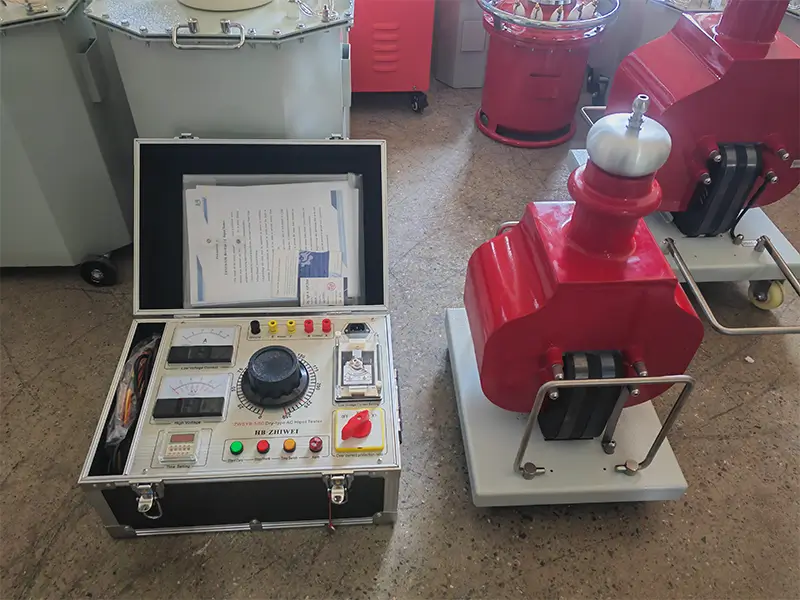
Dry-type testing transformers (such as the ZWDYB series) feature high-grade cold-rolled CD-core or columnar silicon steel cores, with high- and low-voltage coils vacuum-cast into a solid, unified structure using high-dielectric-strength epoxy resin.
1. Core Advantages
Extremely Lightweight and Portable: Eliminates heavy insulating oil and thick-walled steel tanks entirely. For example, a 5kVA/50kV unit weighs only around 45kg—easily transported by two technicians and stored in a standard service vehicle trunk.
Zero Leakage and Maintenance-Free: Contains no liquid fluids and no pressurized gas. There is zero risk of oil spills contaminating clean testing sites during transit, completely eliminating the need for oil filtering, oil replacement, gas replenishment, or gasket maintenance.
Immediate Plug-and-Play Operation: Unlike oil-filled units, dry-type transformers do not require settling time on site to exhaust air bubbles. Technicians can connect the protective ground and begin testing immediately, shortening turnaround times.
2. Limitations and Operational Red Lines
Strictly No Overvoltage (Rigid Breakdown Threshold): If the solid epoxy insulation experiences dielectric breakdown, an irreversible, carbonized discharge path is permanently formed. Physical cracking or electrical puncture scraps the transformer completely, as solid insulation cannot self-heal like oil. Applying test voltages above rated capacity is strictly prohibited.
Limited Maximum Voltage Ceiling: Constrained by resin casting processes and required insulation clearances, single dry-type units are typically limited to 50kV~100kV. Engineering units beyond 150kV presents steep technical challenges and poor cost efficiency.
Unsuitable for Precision “PD-Free” Testing: Microscopic air voids inevitably form during the resin casting and curing process. This gives dry-type units a higher baseline partial discharge level, making them unsuitable for high-sensitivity PD acceptance tests.
Constrained Thermal Dissipation: Solid resin transfers heat slowly. Continuous operation at full rated capacity is typically restricted to ≤30 minutes, requiring mandatory cooldown periods between heavy test runs.
3. Best Application Scenarios
Substation indoor switchgear rooms, high-rise building basements, wind turbine towers, and other facilities with strict fire safety codes and zero-oil-spill rules;
Frequent mobile field service, emergency repairs, and mobile electrical test vans;
Dielectric withstand testing of 10kV and 35kV switchgear cabinets, bus ducts, distribution transformers, and insulated safety tools.
Oil-Immersed Testing Transformers: Advantages, Limitations, and Applications
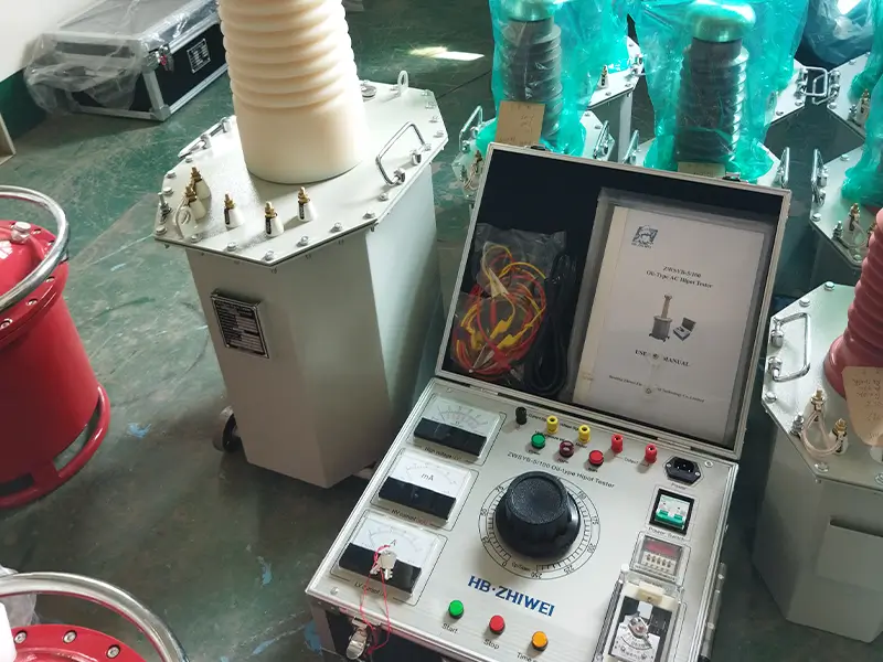
Oil-immersed testing transformers (such as the ZW series YDJ AC series and TDM AC/DC dual-purpose series) are the most established, time-tested baseline equipment in high-voltage testing. The core uses high-grade grain-oriented cold-rolled silicon steel laminations, while the high-voltage winding uses a concentric, multi-layer stepped cylindrical layout. The active assembly is fully immersed in deeply dehydrated, degassed, high-cleanliness mineral insulating oil.
1. Core Advantages
Superior Thermal Dissipation for Continuous Heavy Loads: Natural convective circulation of the transformer oil delivers steady heat exchange, keeping core and winding temperature rises low. Its continuous operating run-time at rated load is more than double that of a dry-type unit, and it can operate continuously under 2/3 rated load.
Surge Endurance and Self-Healing Insulation: Liquid mineral oil features instantaneous self-healing characteristics. If a minor, localized spark discharge occurs during testing, natural convective flow dispels bubbles and restores dielectric strength immediately, making the equipment exceptionally rugged.
Ultra-High Voltage and Heavy Capacity Scalability: Single-tank configurations readily deliver 100kV, 200kV, or even 250kV, with capacities reaching hundreds of kVA. By utilizing multi-unit cascade connections, systems can be linked to generate ultra-high voltages up to several hundred kilovolts.
Low Partial Discharge Background Noise: Upgraded “barrel-type” insulating-cylinder oil transformers (equipped with top-mounted corona grading spheres and exhaust valves) maintain uniform electric field distributions. They suppress internal partial discharge to ultra-low levels (<5pC or even <2pC), making them the classic choice for PD-free test bays.
2. Limitations and Operating Rules
Extremely Heavy Unit Weight: Thick steel tanks filled with high-density mineral oil mean single units easily weigh several hundred kilograms to multiple tons. On-site positioning requires bridge cranes, forklifts, or dedicated heavy casters.
Transit Hazards and Ongoing Maintenance: Prolonged transit vibration can degrade rubber flange gaskets, causing oil seepage. Units require periodic testing for oil dielectric breakdown voltage (BDV).
Critical Operational Rule: Mandatory Settling Time After Transit: Over-the-road transport creates mechanical vibration that introduces microscopic emulsified air bubbles into the transformer oil (bubbles exhibit far lower breakdown strength than the surrounding oil). Powering on immediately upon arrival is strictly prohibited. The unit must rest level on site for 2~12 hours to allow bubbles to exhaust fully before energizing!
3. Best Application Scenarios
Large research institutes, factory routine/type-test bays for equipment manufacturers, and fixed test stations at electric power utilities;
Long-duration power-frequency withstand testing on high-capacitance apparatus, such as large power transformers and high-voltage generator stators;
Cost-sensitive, permanent or semi-permanent installations requiring continuous, heavy-duty service.
SF6 Gas-Insulated Testing Transformers: Advantages, Limitations, and Applications
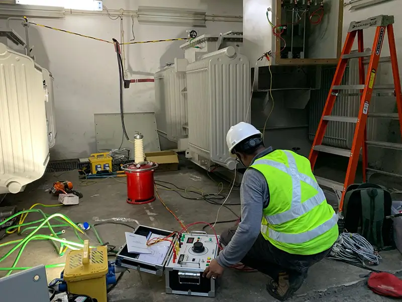
Gas-insulated testing transformers (such as the ZWTYB and YDQ series) represent modern lightweight engineering in high-voltage testing. Built with cold-rolled DQ-151 grain-oriented silicon steel cylindrical frame cores, they utilize high-dielectric, non-combustible sulfur hexafluoride (SF6) gas sealed inside a cylindrical pressure vessel as the primary insulating medium.
1. Core Advantages
Substantial Weight Reduction: Compared to oil-immersed transformers of identical voltage and capacity ratings, SF6 gas-insulated units reduce overall weight by 20%~60%. This removes the requirement for heavy cranes when handling 100kV+ equipment, lowering rigging and field crew costs.
High Single-Unit Voltage Output: Combining the cleanliness of dry units with electric field strength comparable to oil units, a single cylindrical steel tank SF6 transformer can output 200kV~300kV directly.
Low PD Interference and High Cleanliness: SF6 gas is molecularly uniform and pure, producing minimal corona under high voltage stress. The internal sealed assembly does not introduce particulate contamination that triggers discharge, making it well-suited for on-site PD-free testing when paired with partial discharge detectors.
Zero Oil Spills, Zero Settling Time: Eliminates fluid leakage hazards. Upon site delivery, as long as the gas pressure gauge shows normal operating levels, testing can begin immediately without waiting for bubble dispersion.
2. Limitations and Critical Rules
Demanding Enclosure Sealing Standards: Tanks must maintain an operating internal gas pressure of 0.3~0.4MPa over extended service lives. Minor physical permeation can occur over years of use, requiring occasional gas top-ups.
Critical Operational Rule: Check Pressure Gauge Before Energizing: Always inspect the bottom- or side-mounted pressure gauge before raising voltage. If internal pressure drops below 0.3MPa, dielectric strength falls sharply. Energizing under low pressure is strictly prohibited; SF6 gas must be replenished first!
3. Best Application Scenarios
Large utility commissioning projects requiring both ultra-high test voltages (>100kV~300kV) and rapid, flexible transport between test sites;
On-site commissioning and partial discharge testing of Gas-Insulated Switchgear (GIS) and high-voltage XLPE cable terminations;
High-cleanliness chemical complexes, nuclear power stations, and harsh high-altitude or dusty/sandy desert environments.
Core Parameter Comparison Matrix
To assist engineering evaluations and procurement decisions, the following matrix compares the three high-voltage testing transformer types across 8 critical dimensions:
| Parameter | Dry-Type | Oil-Immersed | SF6 Gas-Insulated |
|---|---|---|---|
| Unit Weight and Portability | Lightest (50%~70% lighter than oil units); 2-person carry | Heaviest; (Filled with oil) Requires crane / forklift | Medium-light 20%~60% lighter than oil units |
| Standard Single-Unit Voltage | Typically 50kV~100kV | 50kV~250kV+ (higher with cascade configurations) | 50kV~300kV |
| Baseline Partial Discharge (PD) Level | >20pC ~ 50pC (Not for precision PD tests) | <5pC (Barrel type cylinder) | <5pC ~ 10pC (Highly uniform field) |
| Thermal Dissipation & Duty Cycle | Lower (full rated load ≤0.5h; requires cooldown period) | Exceptional (oil convection circulation; built for continuous heavy loading) | Good (full rated load ≤0.5h; supports continuous operation at 2/3 load) |
| Insulation Self-Healing & Surge Capacity | Poor (no overvoltage permitted; solid puncture causes irreversible failure) | Outstanding (liquid oil self-heals rapidly from transient overvoltages) | Good (gas self-recovers rapidly; robust surge endurance) |
| Maintenance Demands & Intervals | Lifetime maintenance-free; simply keep external insulating bushings clean | Requires periodic oil BDV testing and gasket/valve seal inspection | Requires routine pressure gauge checks; replenish SF6 when pressure <0.3MPa |
| Fire / Explosion & Environmental Risks | Inherently flame-retardant; zero liquid or gas leak risks | Minor fire risk; potential oil leakage and soil contamination during transit | Non-flammable gas; greenhouse gas management protocols apply |
| On-Site Test Readiness | Plug-and-play (zero settling time required) | Settling required (must rest 2~12h after transit to exhaust oil bubbles) | Plug-and-play (test immediately once gas pressure confirms normal) |
4-Step Selection Guide: How to Determine the Right Testing Transformer
Step 1: Determine the Maximum Test Voltage
Identify the maximum required power-frequency AC test voltage (Vtest) specified by regional test standards (such as DL/T 596 or IEC standards) or factory acceptance criteria for the target apparatus.
If testing low-voltage switchgear, busway systems, and ≤35kV insulating hardware, the required test voltage rarely exceeds 100kV. Dry-type units provide clear weight and cost benefits here;
If the test requires ultra-high voltages of 150kV~300kV, evaluate between SF6 gas-insulated and oil-immersed transformers;
Modular High-Voltage Strategy: If 150kV is required on sites inaccessible to heavy cranes, consider multi-stage cascading (e.g., cascading three 50kV units to achieve 150kV).
Step 2: Calculate Required Rated Capacity (kVA) Based on Capacitive Load
During power-frequency withstand testing, the test object functions electrically as a capacitive load (Ct). Undersizing the transformer capacity causes severe output waveform distortion and prevents the system from reaching target test voltages. Conversely, oversizing adds unnecessary weight and procurement costs.
The standard formula for testing transformer nominal capacity (Pn) is:
Pn: Nominal capacity of the testing transformer (kVA)
Vn: Rated RMS high-voltage output of the testing transformer (kV)
ω: Angular frequency of the supply voltage (ω = 2πf; ω ≈ 314.16 at 50Hz)
Ct: Equivalent capacitance of the test object (pF)
K: Engineering safety margin factor (prevents overload and avoids circuit resonance):
· When Vn = 50~100kV, set K = 4;
· When Vn = 150~300kV, set K = 3;
· When Vn > 300kV, set K = 2.
Empirical Capacitance (Ct) Reference Ranges for Common Test Objects:
Suspension / post insulators: Tens of pF
High-voltage bushings: 100~1000pF
Power transformer windings: <1000kVA: ~1000pF; >1000kVA: 1000~10000pF
High-voltage XLPE / paper-insulated cables: Approximately 250~300pF/m
Gas-Insulated Switchgear (GIS): 100~10000pF
Calculation Example: For an AC power-frequency withstand test on an insulating bushing with an equivalent capacitance Ct = 2000pF at a test voltage Vn = 100kV (safety factor K = 4):
The appropriate selection is a testing transformer rated at 30kVA/100kV.
Step 3: Assess Testing Environment and Mobility Frequency
Frequent Field Mobility & Mobile Testing Vans: Prioritize dry-type units (for ≤50kV) or SF6 gas-insulated units (for >100kV). Both eliminate oil leak risks and require no settling wait times after rough transit, saving substantial labor and schedule hours.
Cleanrooms and Explosion-Proof Zones: For nuclear power facilities, clean chemical plants, and data center switchgear rooms where oil drips are strictly prohibited, select dry-type or SF6 gas-insulated designs.
Permanent Laboratories and Substation Transformer Maintenance: Where lifting hoists or cranes are readily available and testing demands high duty cycles, oil-immersed transformers provide long-term durability and the lowest unit-capacity cost.
Step 4: Confirm Partial Discharge (PD-Free) Requirements
If the test procedure only mandates a standard 1-minute Hipot withstand without tripping, all three transformer types are suitable;
If for rigorous type testing or scientific research acceptance where a partial discharge (PD) detector must be coupled simultaneously to monitor the test object’s discharge magnitude at rated voltage (e.g., requiring background noise < 5pC), standard dry-type transformers are strictly prohibited! In these cases, an insulating cylinder PD-free oil-immersed transformer (“barrel type”) or a high-quality SF6 gas-insulated transformer must be used.
Frequently Asked Questions (FAQ)
Q1: Which testing transformer offers the best portability for mobile substation testing?
For standard medium- and low-voltage tests (≤50kV), dry-type testing transformers offer the best portability: they are lightweight, oil-free, easily handled by two technicians, and can be transported horizontally in service vehicles.
If test voltages exceed 100kV up to 200kV~300kV, SF6 gas-insulated transformers are the most portable choice—weighing 20%~60% less than equivalent oil-immersed units, making them ideal for high-voltage field engineering.
Q2: Can an oil-immersed testing transformer be transported on its side? Why must it rest before use?
Never transport an oil-immersed transformer horizontally or tilted! Shipping crates are clearly marked with upward-pointing orientation arrows. Tilting or laying the unit flat causes internal air to migrate between high-voltage winding layers and can cause oil seals to weep. Furthermore, road vibrations during long-distance transit agitate the oil, creating microscopic emulsified air bubbles that have a much lower dielectric strength than the oil itself.
Upon delivery, the unit must stand upright and rest for 2~12 hours so bubbles can vent to the oil surface. Energizing before bubbles disperse risks internal layer-to-layer dielectric breakdown!
Q3: Can an SF6 gas-insulated transformer be energized if pressure drops below 0.3 MPa?
Never energize the unit under low pressure! The dielectric strength of the transformer depends directly on the molecular density of the SF6 gas. When internal gas pressure falls below 0.3MPa, the critical breakdown field strength of internal clearances drops sharply. Forcing a voltage ramp under low pressure will trigger internal surface flashovers across the winding insulation or cause a direct puncture to the tank shell.
Always inspect the pressure gauge before starting. If pressure reads below 0.3MPa, connect an SF6 gas cylinder and refill to 0.3~0.4MPa as specified in the manual before energizing.
Q4: How can we achieve 150kV+ testing if a single transformer is too heavy to move on site?
You can use a multi-unit cascade configuration. By specifying transformers equipped with internal excitation tap windings, two or three mid-sized units can be connected in a cascade series. For example, by cascading three lightweight 50kV transformers, the total output reaches 50 + 50 + 50 = 150kV.
This modular approach breaks down the total weight into manageable units, solving high-voltage test requirements in remote or confined spaces where heavy lifting machinery cannot operate.
EXPERT GUIDANCE
Need Help Choosing the Right Testing Equipment?
Conclusion
As the final verification line for electrical equipment insulation, high-voltage power-frequency withstand testing involves no single universal transformer solution. Optimal selection relies on matching test object capacitance (Ct), maximum required test voltage, and field transport conditions:
choose dry-type for ≤50kV distribution apparatus and rapid inspections; oil-immersed for permanent test halls and long-duration, high-capacity testing; and SF6 gas-insulated for field projects demanding 100kV~300kV ratings, PD-free testing, and high mobility.
As a dedicated manufacturer of high-voltage test equipment, HB ZHIWEI delivers a complete portfolio of high-voltage testing transformers built to IEC 60060-1 and DL/T 848.2 standards:
Rapid Lightweight Field Testing: HB ZHIWEI ZWDYB series dry-type testing transformers—completely oil-free, maintenance-free, and ready to test upon arrival;
Heavy-Duty High-Capacity Testing: HB ZHIWEI YDJ / TDM series oil-immersed testing transformers—supporting extended full-load cycles and multi-unit cascade configurations;
Mobile High-Voltage Field Solutions: HB ZHIWEI ZWTYB series SF6 gas-insulated testing transformers—up to 60% lighter than traditional oil-immersed units, engineered for on-site PD-free testing.
Need capacity sizing and voltage calculations based on your specific test object parameters?
Contact our high-voltage engineering team to receive technical data sheets, cascade system designs, and customized commercial quotations.