
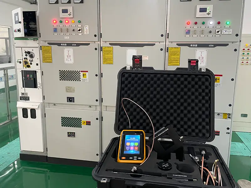
In medium- and high-voltage power distribution systems and industrial plants, insulation breakdown remains the top cause of catastrophic equipment failure. Insulation degradation never happens overnight. Long before a flashover occurs, the dielectric material continuously sends out microscopic warning pulses: Partial Discharge (PD).
Whether you maintain substation assets, manage plant electrical systems, or perform routine predictive maintenance, understanding how partial discharge works and using non-intrusive diagnostic tools is your first line of defense for electrical grid reliability.
What Is Partial Discharge?
According to IEC 60270 standards, Partial Discharge (PD) refers to an electrical discharge that occurs across only a localized portion of the insulation between two conductors, without completely bridging the path between them.
- Complete Breakdown: High-voltage current shorts directly to ground, causing violent arc flashovers, explosions, and circuit trips.
- Partial Discharge (PD): The discharge happens only inside tiny air voids, along edges of impurities, or within micro-cracks in or on the insulation. At this point, the equipment continues to operate at normal service voltage, but the insulation is steadily deteriorating.
Why Do Tiny Air Gaps Discharge Before Solid Insulation?
During manufacturing, mechanical vibration, thermal expansion and contraction, or natural aging, tiny air pockets inevitably develop inside insulating materials.
The relative permittivity of gas (εr ≈ 1) is much lower than that of solid insulation, such as epoxy resin (εr ≈ 3.5 to 5).
Under electromagnetic field theory, materials with a lower dielectric constant endure higher electric field stress (E). Air has a breakdown strength of only about 3 kV/mm, whereas solid insulation can typically withstand more than 30 kV/mm.
Conclusion: At rated operating voltage, the main insulation body is not overloaded. However, the electric field within the air void has already exceeded its limit. As a result, repetitive ionization breakdowns and small spark discharges occur inside the air gap first.
Five Stages of Solid Insulation Breakdown
A single PD event releases very little charge—usually in the picocoulomb (pC) to nanocoulomb (nC) range. But in a 50 Hz or 60 Hz AC electric field, these discharges repeat thousands of times per second, causing irreversible physical and chemical damage to the insulation:
Stage 1: Electrical Stress Concentration
Manufacturing voids, micro-cracks, and boundary impurities distort the local electrical field.
Stage 2: PD Onset
Nanosecond-level pulses occur repeatedly, releasing energetic electrons and ions.
Stage 3: Chemical Attack & Thermal Degradation
Discharges produce ozone (O3), nitrogen oxides, and corrosive acids. Local micro-plasma temperatures can reach several hundred degrees Celsius, eroding the insulation material.
Stage 4: Electrical Treeing
Carbonized micro-channels branch out from the voids to create conductive pathways. The appearance of electrical treeing marks the point of no return—initiating a rapid, irreversible breakdown
Stage 5: Complete Insulation Breakdown
The main insulation fails completely, creating a direct short circuit and catastrophic equipment failure.
Industry Warnings: Key Insights from IEEE and CIGRE Studies
| Research Body / Standard | Key Findings & Statistics | Practical Engineering Impact |
|---|---|---|
| CIGRE WG A2 / B3 Reports | Over 80% of sudden breakdowns in MV/HV transformers and GIS equipment show detectable PD signals weeks or months before failure. | Sudden insulation failures are not truly sudden; they have a latent period and are entirely detectable early on. |
| IEEE Std 493 Reliability Report | Insulation breakdown accounts for more than 75% of failures in switchgear and cable accessories. | The insulation system is the most fragile part of electrical equipment and the primary factor limiting asset life. |
| EPRI Asset Lifecycle Studies | Plants that adopt predictive maintenance (PdM) for PD cut unplanned outages by over 65% and reduce overall maintenance costs by 30% to 50%. | A minor investment in early PD testing easily prevents multimillion-dollar downtime events. |
Key Rule of Thumb: No unusual noise, no burning smell, and no temperature rise—yet discharge could still be happening inside!
Standard infrared (IR) cameras only detect high surface heat caused by loose contacts and high resistance under load. Early internal PD releases very little heat. You need dedicated PD diagnostic instruments to detect these microscopic discharges in their hidden stages.
On-Line PD Testing and Pattern Diagnostics
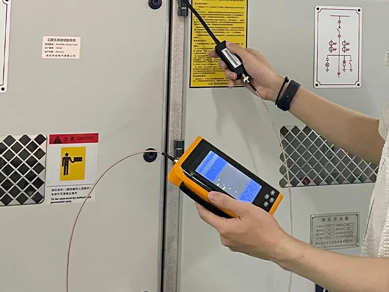
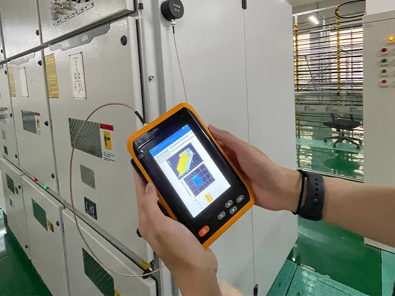
To evaluate equipment condition without taking outages, engineers use on-line sensors such as Transient Earth Voltage (TEV), Ultra-High Frequency (UHF), and Acoustic Emission (AE).
To handle intense background electromagnetic interference in substations, test solutions like the HB ZHIWEI ZWPD92 provide digital filtering and phase-synchronization capabilities. Core pattern analysis tools include:
| Diagnostic Pattern | Working Principle | Field Value |
|---|---|---|
| Time-Domain Waveform | Analyzes the single-pulse shape, rise time, and decay characteristics. | Quickly separates single, isolated noise bursts from continuous, repetitive electrical sparks. |
| PRPD Pattern (Phase-Resolved Partial Discharge) | Maps discharge pulses across the AC power cycle (0° to 360°): • Internal defects: Symmetrical clusters in both positive and negative half-cycles. • Corona discharge: Concentrated near the negative AC peak. • External noise: Scattered randomly across all phases. | Identifies specific defect types and prevents false alarms. |
| PRPS Pattern (Phase-Resolved Pulse Sequence) | Creates a dynamic 3D plot showing “Time - Phase - Amplitude.” | Tracks how discharge severity grows over time and varies with load changes. |
Best Practices for Predictive Maintenance (PdM)
To stop insulation defects from turning into catastrophic failures, implement these maintenance practices:
- Establish Baselines: Run an initial on-line PD test when equipment is newly commissioned or returned to service after a major overhaul. Record baseline numbers and pattern signatures for future comparison.
- Set Up Routine Patrols: Establish quarterly or semi-annual portable testing routes for critical 10 kV to 35 kV switchgear and cable terminations.
- Focus on Trends: Look at trends over time rather than a single absolute reading. If discharge levels double at the same test point under similar operating conditions, or if PRPD patterns change from scattered points to tight, symmetrical clusters, increase testing frequency and schedule an outage for inspection.
Frequently Asked Questions (FAQ)
Q1: What is the fundamental difference between partial discharge and a complete short-circuit breakdown?
Partial discharge is a localized, non-punch-through breakdown that takes place inside tiny air voids, at impurity boundaries, or along surface micro-cracks. Because it does not bridge both conductors, equipment can still run normally on the surface.
A short-circuit breakdown occurs when the insulation loses its dielectric strength completely. Current flashes straight across the conductors, causing violent arcs, protection trips, and severe physical destruction.
Q2: Why can’t thermal imaging cameras replace partial discharge testing tools?
Infrared cameras detect surface heat caused by loose, high-resistance joints under heavy load. In contrast, early-stage partial discharge releases very little energy (typically only picocoulombs to nanocoulombs), generating negligible heat on metal enclosures. Detecting PD requires specialized electromagnetic or acoustic sensors.
Q3: How do you identify real PD signals in noisy industrial environments with high electromagnetic interference?
Engineers rely on PRPD (Phase-Resolved Partial Discharge) and PRPS (Phase-Resolved Pulse Sequence) pattern analysis. Real internal insulation defects pulse in sync with specific phases of the AC cycle (such as symmetrical clusters in both positive and negative half-cycles).
In contrast, external electrical noise, variable-frequency drives, and lighting interference scatter randomly across the entire 0° to 360° phase range.
EXPERT GUIDANCE
Need Help Choosing the Right Testing Equipment?
Conclusion and Next Steps
Partial discharge is the clearest early sign that high-voltage insulation is degrading toward failure. By using non-intrusive on-line testing and pattern analysis, maintenance teams can identify potential risks months before unplanned downtime occurs. Moving from reactive repairs to condition-based maintenance is the most effective way to improve asset reliability and cut operational costs.
For assessing the insulation health of substation switchgear, cable terminations, or transformers, check out the HB ZHIWEI ZWPD92 partial discharge detection system and testing solutions, or contact us for technical specifications and field support.