
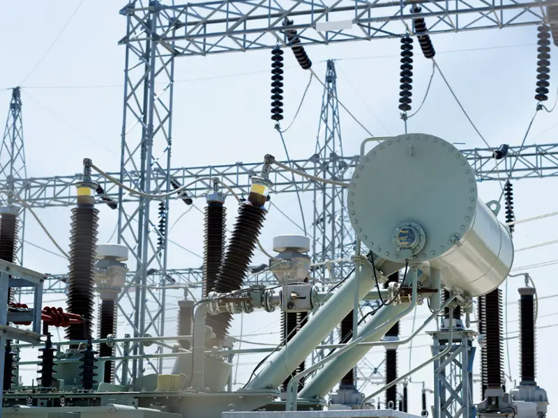
Transformer turns ratio (TTR) testing is a core factory acceptance and field preventive commissioning test used to evaluate transformer winding turns ratios, verify the physical condition of tap changers, and diagnose minor inter-turn short circuits. According to international standards IEEE C57.12.90, IEC 60076-1, and national standard GB/T 1094.1-2022: the measured ratio deviation at all tap positions must be strictly controlled within ±0.5% of the nameplate rated value.
Based on hands-on field engineering experience, this article provides an in-depth analysis of the 7 most critical errors commonly made during transformer turns ratio testing, along with systematic avoidance solutions compliant with international electrical codes.
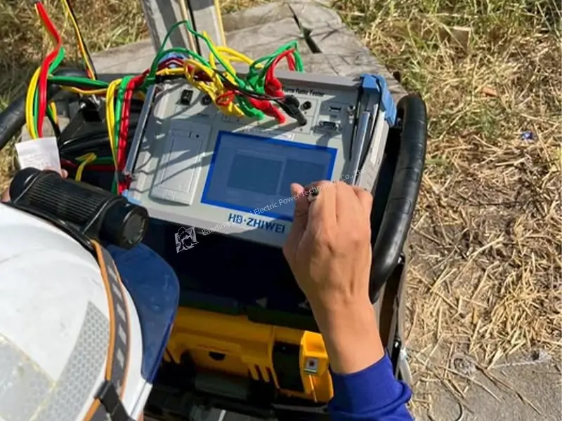
Error 1: Ignoring the Effect of Core Residual Magnetism
Field Trap:
In substation routine testing, technicians typically perform DC winding resistance tests first. After DC current flows through a high-inductance winding, significant residual magnetism remains in the transformer’s silicon steel core. If an AC turns ratio test is performed without demagnetization, the initial alternating flux superimposed on the residual flux will cause the core to instantly enter a nonlinear half-wave magnetic saturation region.
Field Symptoms:
Excitation current surges abnormally by tens of times, phase angle drifts, causing the calculated ratio value to severely exceed the tolerance (far beyond the ±0.5% threshold).
Solution:
Transformer testing must strictly follow the procedure: “demagnetize first, then measure turns ratio.” If DC current was previously applied, a degausser with alternating decaying current must be used to thoroughly demagnetize both the HV and LV cores.
Note: New-generation smart diagnostic instruments, such as the HB ZHIWEI ZWBB201 TTR Tester, integrate advanced reverse microcomputer-controlled signal sources that can automatically suppress residual flux disturbances during AC excitation, significantly reducing misdiagnosis rates caused by flux drift.
Error 2: Testing Only the Rated Tap Position
Field Trap:
To save outage time, some engineers perform a single turns ratio test only at the main tap (e.g., Tap 3 or the rated 10kV/0.4kV position) and declare the transformer acceptable. However, mechanical jamming of De-Energized Tap Changer (DETC) or On-Load Tap Changer (OLTC) contacts, transition resistor burnout, and contact oxidation typically occur at frequently adjusted non-rated edge tap positions.
Solution:
Per regulatory requirements, all tap positions must be tested sequentially:
- Record the measured turns ratio at every tap position
- Calculate the step change rate between adjacent taps and verify it strictly matches the nameplate rated value (e.g., typically ±1.25% or ±2.5% per step)
- Use the automatic tap tracking function of modern instruments to automatically capture and sequentially store the current tap value during adjustment, eliminating missed inspections
Error 3: Incorrect Transformer Vector Group Configuration
Field Trap:
Three-phase transformers have complex winding connection configurations (e.g., Dyn11, Ynd11, YNy0, D/d, etc.). For the industrially common Dyn11 transformer: the HV side is delta-connected (△), the LV side is star-connected, and the LV line voltage lags the HV line voltage by 330°.
If the technician mistakenly selects Yy0 in the instrument, it will calculate based on a mathematical model where line voltage equals phase voltage, causing the result to deviate from the standard turns ratio by a factor of √3 ≈ 1.732.
Solution:
Before testing, verify the vector group on the transformer nameplate. For unknown transformers with missing nameplates or rewired connections, use a tester with blind vector group identification capability.
For example, the HB ZHIWEI ZWBB201 testers support an “Unknown” mode — the instrument automatically demodulates phase differences via programmed three-phase sine waves, automatically identifies the winding group, and displays the HV/LV vector topology diagram in approximately 3 seconds.
Error 4: Ignoring Kelvin Contact Resistance of Test Clips
Field Trap:
Transformer bushing terminals that have been in service are exposed to air for years and develop thick layers of oxide, sulfide, dust, and oil contamination. If simple two-wire single-contact clamps are used, the contact resistance between the test clip and terminal can reach ohm-level values.
On the LV side (where voltage is only tens of volts), contact resistance voltage drop causes serious voltage measurement drops in the LV sampling circuit, resulting in a falsely high calculated turns ratio.
Solution:
- Physical Cleaning: Before connecting, thoroughly remove oxide layers and corrosion from test electrode surfaces with metallographic sandpaper until bare metal is exposed
- Kelvin Four-Wire Measurement: Completely physically separate the voltage detection leads from the current excitation leads, collecting true terminal voltage from the contact root — completely eliminating interference from lead resistance and contact impedance on microvolt-level signals
Error 5: Only Checking Ratio Acceptance While Ignoring Excitation Current Balance
Field Trap:
Many test reports only record ratio error and sign off as long as it falls within ±0.5%. However, transformers can have localized silicon steel sheet insulation damage, core lamination short circuits, or weak inter-turn faults in parallel windings. The ratio value itself may not deviate noticeably, yet the fault area has already formed abnormal micro-circulating currents.
Solution:
During turns ratio testing, simultaneously monitor and compare the symmetry of three-phase no-load excitation currents:
Physical Law for Three-Phase Three-Limb Core:
Due to the significantly shorter magnetic path length of the middle limb (Phase B) compared to the outer limbs (Phases A and C), under balanced three-phase voltage excitation, the normal core’s reluctance exhibits:
RmA ≈ RmC > RmB
- Normal Current Characteristics: Phase A and Phase C excitation currents are approximately symmetric and close to each other, while Phase B excitation current is slightly lower by approximately 15–30%
- Fault Warning: If the excitation current of a single phase suddenly increases to several times that of other phases, even if the ratio calculation error is still within ±0.5%, it indicates a latent localized short circuit defect in the core or winding, requiring further investigation combined with transformer insulation and partial discharge testing
For latent defect analysis, refer to the previous special topic: “What is Partial Discharge, and Why Does It Destroy Your High-Voltage Equipment”
Error 6: Inappropriate Test Excitation Voltage Selection
Field Trap:
Some older testers can only output weak voltages below 10V. In extra-high-voltage substations with severe electromagnetic interference, weak signals are easily overwhelmed by stray coupling from surrounding energized busbars’ spatial power frequency electric fields.
Conversely, blindly applying excessively high power-frequency AC voltage (e.g., exceeding hundreds of volts) could, if an inter-turn shorted winding is present, trigger test arc damage to insulation, or even exceed the portable instrument’s power supply capacity.
Solution:
Per field testing guidelines, select a high-stability microcomputer digital variable-frequency inverter signal source:
- Apply AC 40V–160V stable-frequency, stable-voltage test signal to the transformer HV side (e.g., the ZWBB201 uses a dedicated HV-side AC 40V pure three-phase sine signal)
- Use internal software filtering algorithms to filter out field power grid harmonic disturbances, completely eliminating the traditional drawback of relying on the asymmetric 220V grid voltage as a reference
Error 7: Reversed HV/LV Terminal Connection Causing Step-Up Shock Hazard
Field Trap:
This is the most fatal safety violation in transformer testing. When operating step-up/step-down transformers with large turns ratios (e.g., 110kV/10.5kV or 10kV/0.4kV), the technician mistakenly connects the instrument’s HV output test lead to the transformer’s LV terminal, and the measurement sampling lead (LV) to the HV terminal.
Once the instrument applies excitation voltage to the LV end (even just 40V), according to the electromagnetic induction step-up effect:
UHV = Utest × K
If the turns ratio K=100, the HV bushing will instantaneously induce a lethal voltage exceeding 4000V, easily breaking down the instrument’s LV input sampling board, and potentially electrocuting test personnel!
Solution:
- Strict Color-Coded Closed-Loop Wiring: Yellow (A/a), Green (B/b), Red (C/c), Black (N/n) — HV terminals (uppercase letters/long leads) and LV terminals (lowercase letters/short leads) must be connected strictly per specification
- Hardware-Level Reverse Connection Interlock Protection: Qualified modern TTR testers must have microsecond-level transient reverse connection lockout circuits. When the instrument detects abnormal ratio gain caused by reverse excitation, it must cut off the internal power source within 10ms and trigger audible and visual alarm, preventing step-up hazards at the hardware level
Quick Reference Checklist: Core Parameters vs. International Standards
Test Parameter | Acceptance Standard | Root Cause | Field Engineering Solution |
Turns Ratio Error | Deviation < ±0.5% (IEEE C57.12.90 / IEC 60076-1) | Tap changer misposition; Inter-turn short circuit; nameplate input error | Toggle tap changer and retest; verify with DC resistance comparison; re-check via auto TTR tester |
Vector Group & Phase Angle | Must match clock group (e.g., Dyn11 = 330°) | HV/LV polarity reversed; wrong phase sequence in internal wiring | Check bushing terminal markings; use tester’s auto vector group identification |
Excitation Current Symmetry | Outer phases similar; middle phase 15–30% lower | Residual magnetism; shorted core laminations; localized insulation carbonization | Auto reverse demagnetization; multi-point core ground current and insulation test |
Full Tap Step Uniformity | Step % must match nameplate (tolerance ±10% of step value) | OLTC drive slipping; contact loosening or selector skew | Overhaul OLTC drive mechanism; perform transition resistance and timing test |
Field Engineering: Advanced Edge-Case Troubleshooting
Q1: Can an incipient inter-turn short circuit pass the standard turns ratio test without tripping the ±0.5% limit?
Yes. In high-voltage windings with thousands of turns, a minor fault involving only 1 or 2 shorted turns produces a theoretical ratio deviation well below the standard ±0.5% error threshold, easily yielding a false “Pass”.
However, the localized circulating current within that shorted turn will drastically distort the core’s magnetic symmetry. Technicians should never rely on the ratio error alone; an abnormal spike in single-phase excitation current (typically 2 to 5 times higher than normal phases) is the definitive early warning of an incipient inter-turn breakdown.
Q2: Why do conventional single-phase TTR testers frequently yield erratic errors on five-limb or Scott-connected transformers?
Five-limb cores and specialized traction configurations (such as Scott or Le Blanc transformers) feature asymmetric magnetic flux return paths. Traditional single-phase AC excitation forces flux to circulate uncontrollably through adjacent unexcited limbs, inducing virtual neutral point displacement and skewing phase-to-phase voltage readings.
Accurately testing these configurations requires true three-phase synchronous excitation combined with vector demodulation algorithms to stabilize the neutral potential and calculate true physical turns ratios.
Q3: How do you eliminate false ratio readings caused by strong spatial electrostatic induction in energized 500kV switchyards?
In energized switchyards, spatial power-frequency electric fields easily distort weak test voltages when using legacy testers powered directly from the local commercial grid. To eliminate this interference, deploy an instrument with an internal program-controlled sine wave source (such as the HB ZHIWEI ZWBB201 with AC 12V–160V adjustable output).
This decouples excitation from grid unbalance. Coupled with real-time voltage waveform monitoring and up to 32nd harmonic analysis, engineers can visually isolate substation noise and capture accurate ratio readings.
Conclusion
Transformer turns ratio testing is far more than a routine voltage measurement, it is a critical diagnostic tool for assessing core magnetic circuit condition, tap changer mechanical contact integrity, and winding insulation performance.
Achieving measurement accuracy that strictly complies with IEEE C57.12.90 and IEC 60076-1 standards demands that technicians follow scientifically rigorous procedures: thoroughly eliminating core residual magnetism, testing every tap position sequentially, and carefully comparing three-phase excitation current symmetry.
Eliminating the 7 common errors outlined above requires not only disciplined, standardized operating habits from field test personnel, but also next-generation digital intelligent testing tools capable of removing human misjudgment and proactively safeguarding personal safety.
Upgrade Your Field Testing Experience
To address the challenges of complex substation environments and tight maintenance schedules, we recommend the HB ZHIWEI ZWBB201 Portable TTR Tester.
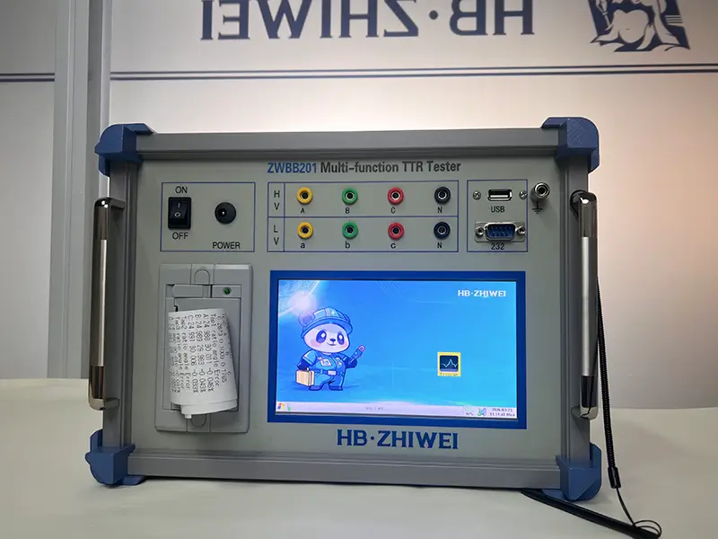
Weighing just 2 kg and purpose-built for efficient, safe field diagnostics, the ZWBB201 eliminates testing risks at the source:
Full Automatic Blind Identification: One-key automatic identification of unknown vector groups (e.g., Dyn11, YNd11, etc.) , completes ratio, polarity, and group determination in approximately 3 seconds, with accuracy up to 0.1% and built-in OLTC tap position auto-tracking.
Three-Phase Stable Frequency & Voltage Signal Source: Internally integrated programmed sine wave inverter source effectively suppresses core residual flux interference, completely free from field grid harmonics and three-phase imbalance, turns ratio measurement range up to 0.8 ~ 50,000.
Hardware-Level HV/LV Reverse Connection Lockout: Built-in microsecond-level transient protection circuit instantly cuts power and triggers an alarm within milliseconds upon detection of reversed HV/LV leads, eliminating step-up induced voltage shock hazards at the hardware level
Visit our official website zwpowertest.com to view full technical specifications and key features, or contact our engineering team directly for a customized solution and dedicated quote!