
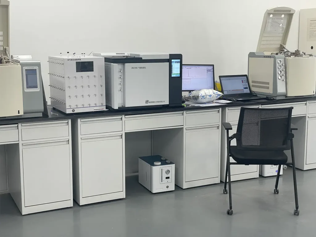
In the lifecycle condition-based maintenance of large oil-filled electrical equipment, Dissolved Gas Analysis (DGA) is globally recognized as the most sensitive “blood test” for detecting incipient internal faults at the earliest stage.
According to international standards such as IEEE C57.104 and IEC 60567, oil-filled equipment experiences localized thermal and electrical stresses during operation. These stresses cause insulating oil and oil-impregnated paper to slowly break down, generating trace amounts of characteristic fault gases—primarily hydrogen (H2), methane (CH4), ethane (C2H6), ethylene (C2H4), acetylene (C2H2), carbon monoxide (CO), and carbon dioxide (CO2).
By using a dedicated laboratory gas chromatograph to achieve high-precision separation and quantitative analysis of characteristic hydrocarbon gases down to 0.1 μL/L (0.1 ppm), engineers can pinpoint the physical nature and severity of internal faults weeks or even months before catastrophic dielectric breakdown occurs.
Table of Contents
The Core Maintenance Pain Point: Why Routine Electrical Tests Cannot Replace DGA
Asset managers often ask: “Our substations already perform regular turns ratio and insulation resistance tests. Why do we still need gas chromatography for transformer oil?”
The answer lies in the different “response windows” of these tests along the fault development timeline.
Insulation Defect Stages vs. Testing Sensitivity
Stage 1: Early Incipient Defects (Micro-discharge and slight localized overheating)
Internal physics: Nanosecond-level corona discharges occur in oil gaps, or burrs on core bolts cause small circulating currents (temperatures <150 °C).
Routine electrical tests: Insulation resistance remains normal, dielectric dissipation factor shows no clear change, and turns ratio passes completely. Routine tests are entirely blind at this stage.
DGA response: Insulating oil molecules are excited by weak electrical stress, releasing high-purity hydrogen (H2) and light alkanes at ppm levels. A gas chromatograph detects these sudden shifts immediately.
Stage 2: Mid-Stage Defect Growth (Insulation carbonization and solid paper degradation)
Internal physics: Discharges develop into continuous sparking, or poor contact on metal joints causes overheating between 300 °C ~ 700 °C. The degree of polymerization (DP) of the insulating paper drops sharply.
Routine electrical tests: As discussed in our previous guide (High-Voltage Insulation Resistance Testing: PI/DAR and Ramp Tests), the absorption ratio and polarization index may show slight decay. However, because of the large oil volume, overall insulation resistance remains high and often passes testing.
DGA response: Ethylene (C2H4) rises noticeably, accompanied by significant amounts of CO and CO2 from degrading paper. Standard gas ratio methods (such as Rogers or IEC ratios) can clearly identify the fault mechanism.
Stage 3: Late-Stage Breakdown (Turn-to-turn short circuits and power arcs)
Internal physics: Turn-to-turn insulation burns through completely, generating power-frequency short-circuit arcs of thousands of amperes. The oil boils violently, tripping the Buchholz relay.
Routine electrical tests: As noted in 7 Common Errors in Transformer Turns Ratio (TTR) Testing, turns ratio errors will now far exceed ±0.5%. However, irreversible mechanical damage, fire, or explosion has usually already occurred.
DGA response: High-energy arcing produces an explosive surge of acetylene (C2H2).
Conclusion: Insulation resistance and turns ratio tests are basic go/no-go checks to confirm whether a transformer can be energized. In contrast, DGA is your primary predictive line of defense throughout the equipment’s entire operating life.
The “Chemical Fingerprints” of 7 Fault Gases and Their Mechanisms
Mineral insulating oil is a complex blend of alkanes, cycloalkanes, and aromatic hydrocarbons rich in carbon-hydrogen (C-H) and carbon-carbon (C-C) covalent bonds. Solid insulation consists mainly of cellulose molecules in pressboard. Because different chemical bonds require different activation energies to break, the chain lengths and saturation of the resulting gases follow strict physical and chemical rules:
1. Hydrogen (H2): The Earliest Indicator of Electrical Ionization and Partial Discharge
Cracking Mechanism: C-H bonds have relatively low bond energy (around 338 kJ/mol). Under low electric field stress or faint corona discharge (Partial Discharge), energetic electrons break off hydrogen radicals, which quickly recombine into H2.
Typical faults: Ionization in tiny internal gas bubbles, weak surface discharges across oil gaps (see our guide What Is Partial Discharge (PD) and Its Destruction Mechanism for details), or moisture-induced hydrolysis.
2. Methane (CH4) and Ethane (C2H6): Products of Low-Temperature Overheating (<300 °C)
Cracking Mechanism: When localized overheating occurs, C-C single bonds break and recombine into saturated alkanes. Under mild thermal stress between 150°C and 300°C, methane and ethane are the primary products.
Typical Faults: Tank wall eddy current heating caused by poor magnetic shielding, or restricted localized oil circulation in narrow cooling channels.
3. Ethylene (C2H4): The Marker for High-Temperature Overheating (>700 °C)
Cracking Mechanism: As hotspot temperatures rise to 500°C–800°C, saturated alkanes undergo dehydrogenation to form alkene compounds with carbon-carbon double bonds. A sharp rise in ethylene is a definite indicator of severe bare-metal overheating.
Typical Faults: Tap changer contact spring fatigue leading to high contact resistance, poor soldering or loose crimping on lead joints, or degraded core lamination insulation causing circulating eddy currents.
4. Acetylene (C2H2): The “Red Alert” for High-Energy Arcing (>800 °C)
Cracking Mechanism: Forming carbon-carbon triple bonds requires high chemical activation energy (temperatures between 800°C~1200°C or higher in localized micro-plasmas). Normal overheating cannot generate acetylene. It forms only during sparking, circulating spark currents, flashovers from energized high-voltage leads to ground, or sustained turn-to-turn arcs.
Action Threshold: Under standard guidelines, detecting even trace amounts of acetylene (as little as 1~ 5 μL/L) in main tank oil is an extremely dangerous signal. You must immediately begin close monitoring or arrange an emergency scheduled outage!
5. Carbon Monoxide (CO) and Carbon Dioxide (CO2): Indicators of Solid Paper Aging
Cracking Mechanism: These gases originate from the breakdown of glucosidic bonds in cellulose paper. Since transformer oil contains dissolved oxygen, thermal aging of the paper releases both CO and CO2.
Aging Diagnosis Indicators: Technicians usually focus on their relative ratio. Abnormal ratios signal different problems: when CO2/CO < 3, it points to severe localized overheating of the insulating paper; when CO2/CO > 10 alongside large amounts of hydrocarbons, it indicates widespread transformer overheating and accelerated loss of solid insulation life.
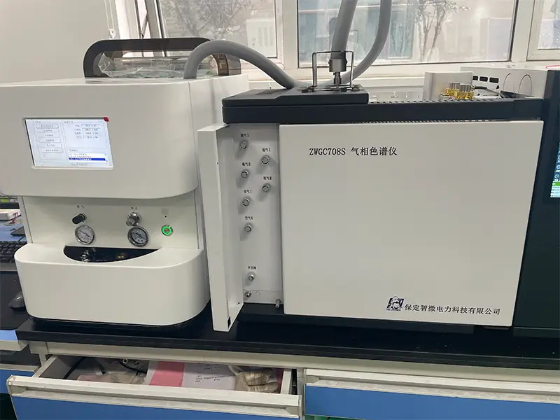
The Complete Gas Chromatography Workflow
Phase 1: Carrier Gas Delivery and Multi-Stage Deoxygenation
Cracking Mechanism: These gases originate from the breakdown of glucosidic bonds in cellulose paper. Since transformer oil contains dissolved oxygen, thermal aging of the paper releases both CO and CO2.
Aging Diagnosis Indicators: Technicians usually focus on their relative ratio. Abnormal ratios signal different problems: when CO2/CO < 3, it points to severe localized overheating of the insulating paper; when CO2/CO > 10 alongside large amounts of hydrocarbons, it indicates widespread transformer overheating and accelerated loss of solid insulation life.
Phase 2: Micro-Sample Injection and Vapor Transfer
Sample Preparation: Using a glass syringe or an automated oscillating degasser, 0.5 to 1.0 mL of equilibrium headspace gas is extracted from the transformer oil sample.
Injection & Vaporization: The sample is injected into the GC inlet system. The instrument supports manual micro-syringes, pneumatic 6-port valves, and automated 10-port gas valves. The inlet vaporization chamber uses independent microcomputer temperature control to ensure all components transfer instantly into the carrier gas stream without secondary thermal cracking.
Phase 3: Molecular Separation in the Isothermal Column Oven
Temperature Control: The sample moves into a temperature-controlled column oven featuring 8-channel independent control (±0.1 °C stability) and 16-step temperature programming.
Physical Separation Mechanism:
- Pre-separation column: Carrier gas sweeps the gas mixture into the pre-column, quickly splitting and eluting the matrix gas stream.
- Dedicated polar packed column: The gas mixture separates as components flow through the column based on molecular weight, boiling point, and adsorption polarity. Components with weak adsorption elute first, while heavier components with strong adsorption elute more slowly. This physically separates all 7 characteristic gases in a clear time sequence.
Phase 4: Dual-Channel Parallel Detection
After separation, the flow splits into two dedicated detection channels:
Channel A: Thermal Conductivity Detector (TCD) for Inorganic Permanent Gases
Hardware Unit: Micro-cell Thermal Conductivity Detector (TCD).
Target Gases: Dedicated to detecting hydrogen (H2), oxygen (O2), and nitrogen (N2).
Core Reaction Mechanism: The heart of the TCD consists of high-resistance tungsten-rhenium filaments placed across the four arms of a Wheatstone bridge. The bridge stays balanced as high-purity carrier gas flows through the reference cell.
Because hydrogen (H2) has a thermal conductivity several times higher than other gas molecules, even trace hydrogen passing through the sample cell causes a sudden change in filament heat dissipation. This unbalances the bridge resistance and generates a millivolt-level signal. The ZWGC808 TCD achieves a sensitivity of S ≥ 10,000 mV·mL/mg, ensuring low-concentration hydrogen is never missed.
Channel B: Methanizer and Flame Ionization Detector (FID) for Hydrocarbons and Carbon Oxides
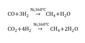
Hardware 1: Nickel Catalyst Methanizer (Held at 360 °C)
- The Challenge: Carbon monoxide (CO) and carbon dioxide (CO2) are inorganic oxygenates and cannot ionize directly in a flame ionization detector (FID).
- Chemical Reaction: In a hydrogen-rich environment over a pure nickel catalyst at 360°C, CO and CO2 undergo a 100% online, high-temperature methanation reduction:
Hardware 2: Flame Ionization Detector (FID)
- Target Gases: Methane (CH4), ethane (C2H6), ethylene (C2H4), acetylene (C2H2), plus the CO and CO2 converted by the methanizer.
- Measurement Principle: Hydrocarbon components enter a high-temperature hydrogen flame (fueled by hydrogen and pure air) and ionize under a 200V polarizing field to generate carbon cations. This ion stream hits the collector electrode, producing a tiny picoampere (pA) current that is directly proportional to the carbon mass concentration. With a detection limit ≤ 5 × 10^-12 g/s, the FID easily breaks through sub-ppm trace detection limits.
Phase 5: High-Speed Digital Sampling and Automated Reporting
Detector currents and voltages feed directly into an integrated 24-bit, low-noise analog-to-digital (A/D) board. The digital signal transmits over industrial Ethernet to the chromatography workstation. The software automatically corrects baseline drift, identifies peaks by retention time, calculates concentrations by peak area, and generates a comprehensive DGA report.
Gas Chromatography Flow Path and Component Reference Guide
| Hardware Module | Operating Condition | Core Function | Target Gases / Goal |
|---|---|---|---|
| Carrier Supply & Purifiers | Purity ≥99.999%, 0.5 MPa pressure | Mobile phase supply; 5A sieves remove moisture and trace O₂ | Stable N₂ / He base flow |
| Inlet & Injection System | Gas-tight syringe or 6-port valve (0.5–1.0 mL) | Transfers extracted gas into the flow stream without sample loss | Headspace gas sample |
| Column Oven & Packed Columns | 8-channel control(±0.1 °C), 16-step ramp | Separates 7 target gases based on molecular polarity and retention | Gas component separation |
| Thermal Conductivity Detector (TCD) | W-Re bridge, sensitivity ≥10,000 mV·mL/mg | Detects thermal conductivity differences across a Wheatstone bridge | H₂ , O₂ , N₂ |
| Nickel Methanizer | Constant 360 °C ±0.1 °C, nickel catalyst | Catalytic hydrogenation of carbon oxides into methane | CO , CO₂ |
| Flame Ionization Detector (FID) | H₂ / dry air flame, detection limit ≤5 x 10⁻¹² g/s | Flame ionization of hydrocarbons measured by picoammeter | CH₄ , C₂H₆ , C₂H₄ , C₂H₂ , and converted CO/CO₂ |
| Built-in 24-bit A/D Board | 20 samples/sec, shielded enclosure | Converts analog signals to digital at the source, shielding substation EMI | Drift removal & peak integration |
HB ZHIWEI ZWGC808: Intelligent Networked Gas Chromatograph for Modern Power Labs
To meet the high-throughput testing demands of utility labs, power plants, and industrial facilities, HB ZHIWEI developed the industrial-grade ZWGC808 Transformer Oil Gas Chromatograph. The system breaks free from the limitations of standalone legacy units.
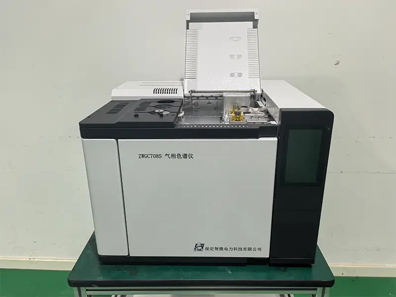
Core Advantages and Customer Value:
1) Fast/Gigabit Ethernet with “Three Independent IPs”
No hardware silos: With built-in IEEE 802.3 TCP/IP hardware, a single central PC can monitor and manage dozens of chromatographs over a local network, saving bench space and computing costs.
Three-tier access: The network board can host three independent IP addresses:
- Operator IP: For benchtop testing, sample injection, and raw data handling.
- Supervisor IP: Allows lab managers or chief engineers to review run progress and diagnostic results remotely.
- System IP: Feeds data directly into plant DCS or dispatch platforms via standard MODBUS/TCP protocols.
2) 8 Independent Heating Zones and Auto Rear-Door Fast Cooling
Features 8 microcomputer-controlled temperature zones with ±0.1 °C precision.
Supports 16-step temperature ramps. After a run completes, the rear oven door automatically cracks open while a quiet, high-volume fan purges hot air. The oven returns to ambient startup conditions within minutes, cutting cycle wait times by more than 40%.
3) Built-In Interlocks to Prevent Component Damage
TCD filament dry-burn protection: TCD filaments can burn out in seconds if powered on without carrier gas. The ZWGC808 resets TCD bridge current to 0 mA on boot. Current cannot be enabled until sensors confirm carrier gas pressure and oven temperatures are fully stable.
FID auto-flameout shutoff: The system continuously monitors baseline current. If the flame blows out, it automatically shuts off the hydrogen supply, preventing flammable gas buildup inside the lab.
4) 8-Inch True-Color Touchscreen
Replaces old mechanical switches with an 8.0-inch color touch interface and built-in keyboard.
Supports hot-plugging, allowing it to double as a handheld terminal for parameter adjustments and system diagnostics directly at the bench.
3 Best Practices for GC Lab Operation and Maintenance
High-accuracy analysis depends both on instrument build quality and consistent standard operating procedures (SOP):
Rule 1: Strictly Follow Startup and Shutdown Sequences
Startup: Always follow this sequence: Turn on carrier gas → Set temperature zones → Let temperatures stabilize → Enable detector current / ignite flame.
Always purge the columns with carrier gas for at least 15 minutes to clear out air before powering the TCD bridge, or the tungsten filaments will quickly degrade.
Shutdown: Always follow this sequence: Turn off detectors (disable TCD bridge current, close H2/air to extinguish FID) → Turn off all heating zones → Wait for the oven and detectors to cool near room temperature → Shut off carrier gas.
Rule 2: Perform Regular System Leak Checks
Whenever you change a gas cylinder, replace an injection septum, or install a new column, run a static pressure hold test. Power down the unit, adjust cylinder regulators so carrier gas reads 0.5 MPa, H2 reads 0.4 MPa, and air reads 0.5 MPa, then close the instrument inlet valves. The pressure gauges should show zero drop over a 10-minute hold.
Rule 3: Maintain Septa and Regenerate Molecular Sieves
Septum Care: High-temp silicone injection septa degrade and leak after repeated piercings. Replace the septum every 50 to 100 injections.
Purifier Regeneration: The 5A molecular sieves in carrier purifiers eventually saturate with moisture. Remove the packing quarterly and bake it in a muffle furnace at 350 °C for 4 hours to restore its absorption capacity.
HB ZHIWEI ZWGC808 Technical Specifications
| System Parameter | Specification |
|---|---|
| User Interface | 8.0-inch color LCD touchscreen, hot-swappable handheld operation, multi-language interface |
| Independent Temperature Zones | 8 zones (Oven, Inlet 1, Inlet 2, Inlet 3, Methanizer, TCD, FID 1, FID 2) |
| Temperature Range & Accuracy | Ambient +4 °C~450 °C, 1 °C steps, ±0.1 °C stability |
| Temperature Programming | 16-step ramp, 0.1 ~ 60 °C/min rate; automated rear-door cooling mechanism |
| Flame Ionization Detector (FID) | Detection limit ≤5 × 10⁻¹² g/s (hexadecane/isooctane); baseline noise ≤0.07 pA; dynamic range ≥10⁶ |
| Thermal Conductivity Detector (TCD) | Sensitivity S≥10,000 mV·mL/mg (benzene/toluene); baseline drift ≤30 uV/30 min; supports 1x/2x/3x/4x digital gain |
| Nickel Catalyst Methanizer | Controlled at 360 °C, conversion efficiency ≥98%, low dead-volume design |
| Detector Expansion | Supports up to 3 detectors simultaneously; optional ECD, FPD, and NPD |
| Signal Acquisition | Internal 24-bit low-noise high-resolution A/D module with automatic baseline correction |
| Communications & Protocols | Industrial 100M/1000M Ethernet (IEEE 802.3); supports MODBUS/TCP for direct DCS integration |
| Power Supply | Single-phase 220V AC ±10%, 50Hz±0.5Hz; minimum power rating 2500 W |
Frequently Asked Questions (FAQ)
Q1: Why do transformers that pass routine electrical tests still require DGA testing?
Routine tests (such as insulation resistance and turns ratio) mainly detect advanced or terminal faults. They cannot see early micro-discharges (<150 °C) or mild local overheating. DGA detects dissolved gases down to 0.1 ppm, identifying faults weeks or months before the main insulation suffers permanent breakdown.
Q2: What does finding trace acetylene (C2H2) in transformer oil indicate?
Forming carbon-carbon triple bonds requires temperatures above 800 °C to 1200 °C, which normal thermal overheating cannot generate. Even tiny amounts of acetylene (1 ~ 5 uL/L) in main tank oil indicate active high-energy arcing, heavy sparking, flashover, or turn-to-turn breakdown. This requires immediate investigation or an urgent scheduled outage.
Q3: Why does a gas chromatograph need a nickel methanizer to measure CO and CO2?
Carbon monoxide (CO) and carbon dioxide (CO2) are inorganic oxygenates that do not ionize in an FID flame. By running the sample through a nickel catalyst methanizer at 360 °C in a hydrogen stream, both gases convert completely into methane (CH4), allowing the FID to measure them with high sensitivity.
Q4: How do I protect TCD tungsten filaments from burning out?
TCD filaments burn out in seconds if powered without carrier gas flow. Always follow the proper sequence: purge the system with carrier gas for at least 15 minutes before applying detector current. At shutdown, turn off detector current before stopping carrier gas. The ZWGC808 includes built-in safety interlocks that lock bridge current at 0 mA until gas flow and temperatures are verified.
EXPERT GUIDANCE
Need Help Choosing the Right Testing Equipment?
Conclusion and Technical Support
Incipient faults in oil-filled transformers develop quietly. Routine Dissolved Gas Analysis (DGA) according to IEEE C57.104 and IEC 60567 standards remains the most reliable way to prevent catastrophic failures.
With sub-ppm detection sensitivity, 8 precision heating zones, and multi-tier network connectivity, industrial-grade chromatographs allow maintenance teams to identify early fault gases accurately and keep power grids running reliably.
To request a laboratory setup plan, SOP documentation, or complete technical specifications for the HB ZHIWEI ZWGC808, visit the official HB ZHIWEI website at zwpowertest.com to connect with our engineering team.