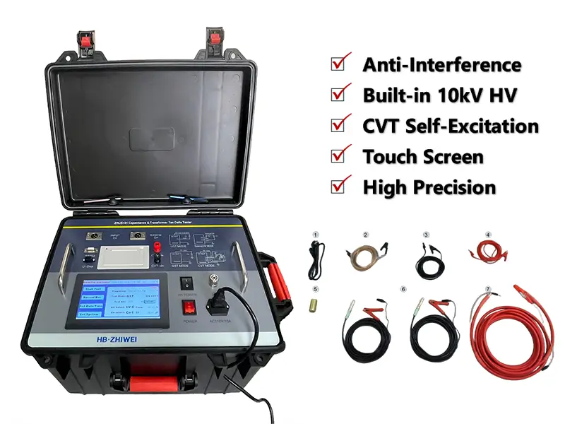
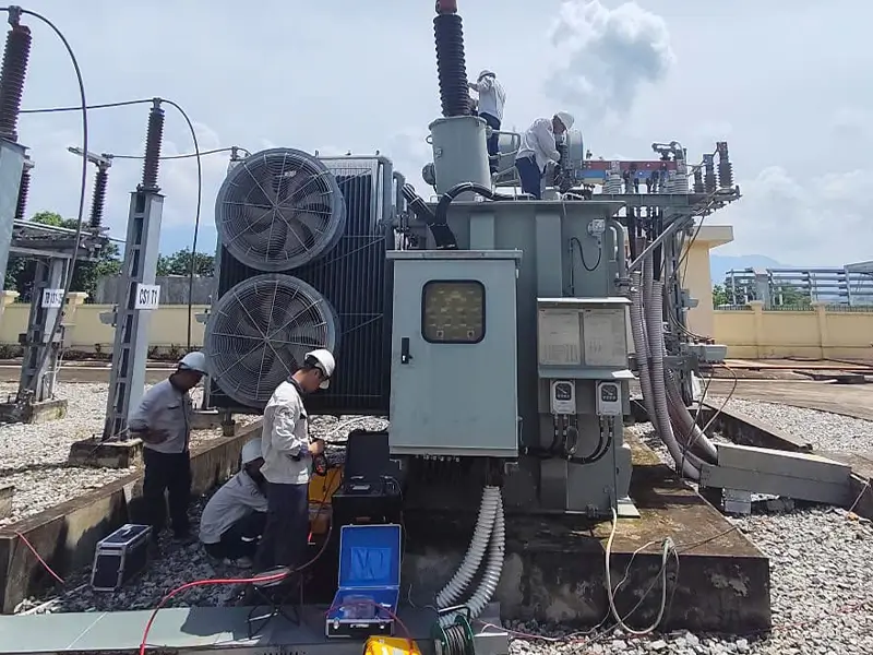
In high-voltage electrical insulation testing, issues such as erratic data fluctuations, “negative tan delta” readings, or CVT measurements deviating significantly from nameplate values are quite common. Statistics show that over 85% of these test anomalies stem from strong on-site electromagnetic interference, environmental temperature and humidity, or improper wiring—not instrument hardware failures.
Accurate diagnosis starts with standardized operation. If you need to review or verify standard test wiring (UST / GST / CVT Self-Excitation method), please refer to the ZWJS101 Tan Delta Tester Standard Operation and Wiring Guide.
This guide tackles common pain points in substation testing, systematically reviewing the 10 most frequent tan delta testing faults and troubleshooting methods to provide a complete emergency solution from external checks to closed-loop verification.
I. 10 Common High-Voltage Tan Delta Testing Faults and Troubleshooting Methods
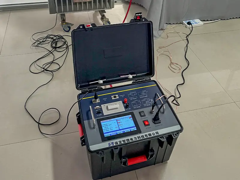
Fault 1: Wildly Fluctuating Data and Poor Repeatability
Common Causes:
- The red high-voltage output clamp or the Cx measuring clamp has poor contact, often clamped onto metal scale, anti-rust paint, or heavy oil stains.
- The HV plug or Cx aviation socket is not fully inserted and locked.
- The test site is near strong alternating electric fields (e.g., directly under energized busbars), allowing power-frequency interference into the sampling circuit.
- The instrument grounding wire has a loose connection, causing high-frequency ground potential floating.
Solutions:
- Stop boosting voltage immediately and fully discharge the test specimen.
- Clean off paint, rust, and oxide layers from the terminals until bare metal is exposed.
- Check and securely re-plug all high- and low-voltage test connectors on the instrument panel.
- Check the crimping point of the dedicated ground wire to ensure a tight connection to the grounding grid.
- In the instrument menu, switch the test mode from “Single Frequency” to the 45Hz/55Hz automatic dual-frequency anti-interference mode.
Fault 2: Instrument Fails to Boost Voltage or Frequently Triggers Protection After Pressing “Start”
Common Causes
- Ground Protection Triggered: The instrument performs a power-on ground self-check and refuses to boost voltage if the ground wire is disconnected or ground resistance is too high.
- The external input power supply voltage fluctuates outside the allowable range (180–270 VAC).
- The HV selector switch is set to “External HV”, but the internal HV source is actually being used.
Solutions
- Check the resistance between the instrument ground terminal and the grounding grid, clean rust off the grounding point, and retighten the ground wire.
- Verify that the power supply voltage is within 180–270 VAC.
- In the instrument menu, verify that [HV Selection] is set to “Internal HV”.
- If rebooting the unit, wait at least 1 minute for internal capacitors to discharge completely before turning it back on.
- Safety Warning: Never bypass the fuse or replace it with an oversized fuse!
Fault 3: “Negative Tan Delta” (tanδ < 0) in Test Results
Many test engineers suspect instrument failure when seeing negative tan delta, but this is typically a physical and wiring interference phenomenon in high-voltage testing.
Typical Scenarios and Causes
- Direct measurement of a CVT lower coupling capacitor: Affected by the internal electromagnetic unit, direct measurement using standard UST/GST wiring easily produces negative values.
- Moisture in electromagnetic PT secondary terminal shielding: Moisture creates a tiny “T-type resistor-capacitor network” inside the specimen, causing phase reversal.
- High ambient humidity (> 85%): Condensation forms a continuous water film on the porcelain bushing surface, creating surface leakage current that disrupts the sampling phase angle.
- Strong electric field induction interference: Testing beneath live busbars introduces power-frequency induced current into the sampling circuit, which vector-adds with the capacitive current and results in a calculated negative phase angle.
Recommended Solutions
- For Capacitor Voltage Transformers (CVTs), always use the built-in CVT Self-Excitation Method.
- Use hot air to dry damp PT terminal boxes and lower bushing sections.
- Clean the specimen surface and install a copper shielding wire (guard ring) around the porcelain bushing to drain surface leakage current.
- Turn on the 45Hz/55Hz automatic dual-frequency anti-interference mode. If interference is severe, appropriately increase test voltage within the insulation’s safe limits (e.g., up to 10 kV) to improve the signal-to-noise ratio (SNR).
- Adjust test lead routing to eliminate distributed capacitance caused by leads dragging on the ground.
Fault 4: Highly Unreasonable Measurement Results on CVT (Capacitor Voltage Transformer)
A CVT consists of a high-voltage capacitor divider (C1), a medium-voltage divider capacitor (C2), and an electromagnetic unit. It cannot be tested with simple standard capacitor or bushing wiring.
Key Inspection and Operating Points
- Mode Selection: Explicitly select the “CVT Self-Excitation” mode in the ZWJS101 menu.
- Bus Grounding Status Verification:
- If C1 is a single-section capacitor, the bus side must strictly remain ungrounded.
- If C1 consists of multiple sections in series, combine conventional UST/GST wiring with the self-excitation method according to the sectional scheme.
- Suspend HV Leads: CVT testing is extremely sensitive to stray capacitance. High-voltage test leads must be suspended using insulating ropes throughout testing and must never drag on the ground or touch metal structures.
Fault 5: Instrument Triggers Protection or Freezes When Powered by a Generator
Common Causes
Small portable gasoline generators used in remote or unpowered substations often produce severe voltage waveform distortion, high-frequency spikes/harmonics, and frequency drift under load.
Solutions
- Use a pure sine wave inverter generator with a rated power of ≥ 3 kW.
- Add an appropriate power filter at the generator output.
- Ensure input power meets 180–270 VAC, 50 Hz ± 1%.
- If available, connect to a stable 220V utility supply from the substation maintenance box.
Fault 6: Measured Tan Delta (tanδ) Is Abnormally High
Common Causes
- Severe contamination or moisture on the porcelain bushing surface; grease, dust, or rust on terminals.
- Local micro-corona discharge between the HV test clamp and the specimen electrode.
- The HV lead is too close to grounded structures, causing active power loss from air ionization.
Recommended Troubleshooting Steps
- Clean and dry the external insulation skirts of the test object.
- Remove paint, rust, and oxidation from terminal connection surfaces.
- Retighten the HV test clamp to ensure full, solid contact.
- Route HV leads so that clearance to ground and nearby metal structures is greater than 1.5 meters.
- Retest and compare results with historical data for the same equipment.
Fault 7: Capacitance Displays as Zero or No Current Feedback
Common Causes
- Internal open circuit in test cables.
- In UST mode, the low-voltage Cx lead is disconnected or the red signal clip fell off.
- In GST mode, the Cx signal lead was mistakenly plugged in and connected to ground.
Solutions
- After fully powering down and discharging, use a digital multimeter continuity/buzzer mode to check core continuity and shield insulation resistance on both HV and Cx cables.
- Double-check that the test mode matches field wiring (Cx must be connected in UST; Cx remains disconnected/floating in GST).
- Verify continuity between the specimen’s HV terminal and its internal winding/capacitor core.
Fault 8: Huge Discrepancy Between Current Test Data and Historical Data
Insulation tan delta depends heavily on temperature and test conditions. Do not judge insulation degradation solely on a single deviated value.
Key Checks:
- Temperature Conversion: The tan delta of insulating oil and oil-impregnated paper increases with temperature. Always convert the current test value to the reference temperature (typically 20°C).
- Test Voltage and Frequency: Verify that test voltage and frequency match historical records.
- Wiring Method: Confirm whether UST or GST was used previously (they measure different insulation zones).
Fault 9: Measurement Drift Due to Aging or Damaged Test Cables
Dragging and running over shielded HV cables in harsh field environments can lead to:
- Broken core wire;
- Short circuit between core wire and shield;
- Poor plug contact;
- Abnormal shield grounding;
- Surface contamination on insulation.
Maintenance Tips
- Regularly check the DC insulation resistance of test cables.
- Coil cables in large, gentle loops during storage; avoid sharp bends, tight knots, or heavy objects on top.
- When testing high-precision objects like standard capacitors, use fully shielded connectors and proper shield connections to minimize stray capacitance effects.
Fault 10: Suspecting an Internal Instrument Failure
If all external factors have been eliminated and the instrument is still suspected, follow these standard steps for closed-loop self-verification:
- No-Load Voltage Boost Test: Unplug all test cables, turn on internal HV testing, and observe whether voltage rises smoothly without abnormal arcing noises.
- Standard Capacitor Verification (Core Method):
1) Take a standard capacitor with known capacitance and tan delta (e.g., 1000 pF, tanδ ≤ 0.005%).
2) Measure it using UST mode first, and compare the result with the nameplate value.
3) Ground the capacitor casing, retest in GST mode, and compare results. - If both UST and GST readings are within allowable tolerance, the instrument is functional, and the issue lies in field wiring or the specimen.
- If readings deviate significantly from standard specs, stop using the instrument immediately and contact the manufacturer for support.
II. Quick Systematic Troubleshooting Workflow
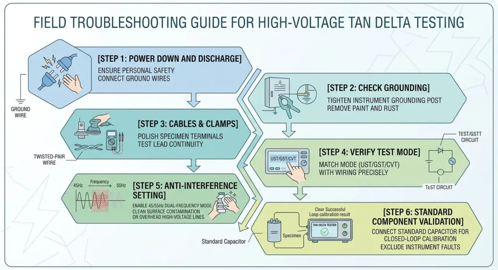
When encountering abnormal test data, avoid dismantling wiring blindly. Follow this troubleshooting sequence:
- First, ensure the test object is completely de-energized, fully discharged, and reliably grounded;
- Next, clean rust and paint off terminals and grounding points; inspect HV/LV cable continuity and ensure clamps are secure;
- Strictly verify that the instrument mode (UST / GST / CVT) matches actual on-site wiring;
- In high-interference environments, enable the 45/55 Hz dual-variable frequency mode and suspend high-voltage leads in the air;
- Finally, if doubts remain, connect a standard capacitor with known parameters for a closed-loop verification test to quickly determine whether the issue is external wiring or the instrument itself.
III. How to Improve the Reliability of HV Tan Delta Test Data
To obtain repeatable, comparable, and diagnostically valuable test results, field test personnel should follow these four core principles:
1. Verify Wiring Before Ramping Up Voltage
Do not focus solely on test voltage at the start. Before boosting voltage, strictly confirm:
- Correct wiring method (UST / GST / CVT Self-Excitation);
- Reliable grounding for both instrument and test object;
- Clean, dry bushing surfaces;
- Good contact on HV clamps;
- Proper shielding configuration.
2. Prioritize Variable-Frequency Mode in High-Interference Sites
In substations, switchyards, or industrial sites, 50 Hz power-frequency interference can significantly distort phase angles. Enabling the 45/55 Hz or 55/65 Hz dual-variable frequency mode on the ZWJS101 effectively filters out same-frequency interference to reveal the true tan delta value.
3. Maintain Consistent Test Conditions (Baseline for Trend Analysis)
When analyzing multi-year data trends for the same equipment, keep the following consistent:
- Same test voltage;
- Same test frequency;
- Same wiring method;
- Similar ambient temperature and humidity (converted to the 20°C reference baseline);
- Same surface cleanliness;
- Standardized operating procedures.
4. Do Not Equate Negative Values Directly with Insulation Degradation
Negative tan delta is usually caused by incorrect CVT wiring, damp PT insulation forming a T-network, stray capacitance, improper shielding, or strong electric field induction. When negative values occur, first check testing methodology and environmental interference before concluding that insulation is damaged.
IV. Summary
High-voltage tan delta testing takes place in complex field environments where electromagnetic interference, surface contamination, humidity, and non-standard wiring can easily cause fluctuating readings or false “negative tan delta.” When anomalies occur, avoid jumping to the conclusion of equipment failure. Instead, adopt a systematic diagnostic mindset: “from outside to inside, ground first then wire, eliminate interference before inspecting the tester.”
Mastering solid testing principles—combined with high-precision instruments featuring advanced variable-frequency anti-interference algorithms and comprehensive safety protections (such as the ZWJS101)—enables engineers to cut through field noise and accurately determine the true insulation health of HV electrical equipment.
EXPERT GUIDANCE
Need Help Choosing the Right Testing Equipment?
V. Contact Zhiwei Electric for Professional Support
Baoding Zhiwei Power Technology Co., Ltd. brings nearly 20 years of industry experience. Our core product lines cover: Comprehensive Transformer Testing, Insulating Oil Testing, High-Voltage & Insulation Diagnostic Testing, Circuit Breaker & Switchgear Testing, and more. Committed to cutting-edge electrical testing technologies, our products are exported to dozens of countries and regions worldwide, serving grid companies, power plants, substations, and electrical maintenance testing service providers.
If you encounter challenging data in the field requiring technical support, or need the ZWJS101 Tan Delta Tester specification sheet and latest pricing, feel free to contact us anytime!