
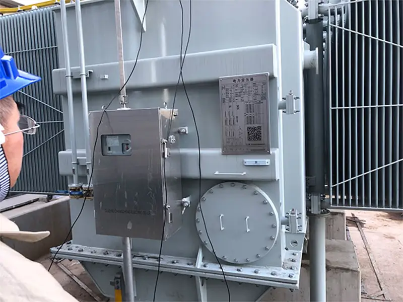
During the preventive testing of substations and high-voltage electrical equipment, insulation deterioration is a major cause of main transformer trips, equipment breakdowns, and even severe accidents. As one of the most effective and sensitive non-destructive testing methods for evaluating high-voltage insulation conditions, the High Voltage Tan Delta Test (or Power Factor Test) can proactively detect early-stage moisture, aging, void discharges, and overall deterioration inside insulation materials.
However, the accuracy of on-site measurements highly depends on standard operating procedures, correct wiring methods (UST/GST), and strict anti-interference measures. Using the ZWJS101 Intelligent Variable Frequency Tan Delta Tester as an example, this article provides a detailed guide on the equipment’s features, test preparations, and an 8-step standard operation procedure to help you efficiently obtain reliable test data on-site.
If you experience severe data fluctuations, negative tan delta values, or abnormal CVT tests during the process, please refer to our troubleshooting guide: Common On-Site Faults and Troubleshooting Solutions.
Core Applications of High Voltage Tan Delta Testing
The dielectric loss tangent (usually expressed as tanδ or tgδ) reflects the proportion of active power loss in an insulating medium under an alternating electric field. The ZWJS101 tester is commonly used for:
- Transformer and reactor insulation testing
- Current and voltage transformer (CT/PT) testing
- Capacitive bushing testing
- CVT (Capacitor Voltage Transformer) testing
- Power capacitor testing
- Surge arrester insulation parameter testing
- Insulating oil tan delta testing
- Electromagnetic and capacitive PT/CT ratio and insulation testing
If the tanδ value of the same type of equipment increases over a long period, or changes significantly compared to historical data, further inspection is usually required to check if the equipment is affected by moisture, aging, contamination, or wiring and shielding issues.
Please note: Tan delta testing is a method for evaluating overall insulation status, which is different from partial discharge location or cable fault location. When test results are abnormal, they should be comprehensively evaluated alongside insulation resistance, winding DC resistance, transformer turns ratio, partial discharge, and visual inspection results.
Core Technical Features of the ZWJS101 Tester
The ZWJS101 utilizes a digital variable frequency power supply, a high-speed DSP chip, and digital filtering algorithms. It features strong resistance to power frequency electromagnetic interference, designed specifically for complex, high electric field environments in substations.
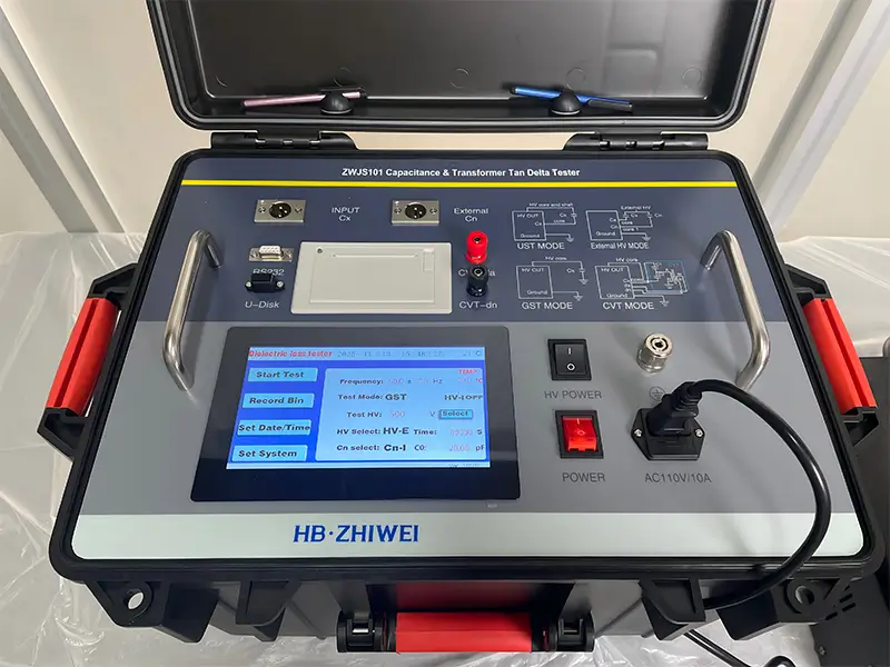
Main Features:
- Multi-level high voltage output: Built-in step-up transformer, supporting up to 10 kV / 12 kV internal high voltage output.
- Variable frequency anti-interference: Supports 40–70 Hz single frequency and 45/55 Hz, 55/65 Hz automatic dual variable frequency testing to eliminate power frequency interference.
- Multiple test modes: Supports Ungrounded Specimen Test (UST), Grounded Specimen Test (GST), GST with guard (GST-g), and CVT self-excitation testing.
- Comprehensive safety interlocks: Built-in protections for poor grounding, overcurrent, and rapid shut-off against high voltage shock.
- Data management: Large touchscreen interface, built-in thermal printer, supports USB data export and RS232 connection for management.
Technical Specifications
| Item | Specification |
|---|---|
| Capacitance Measurement Accuracy | ±(Reading × 1% + 1 pF) |
| Tanδ Measurement Accuracy | ±(Reading × 1% + 0.00040) |
| Capacitance Measurement Range | Internal HV: 3 pF – 60,000 pF / 10 kV; 60 pF – 1.5 μF / 0.5 kV |
| External HV Measurement Range | 3 pF – 1.5 μF / 10 kV; 60 pF – 30 μF / 0.5 kV |
| Tanδ Resolution | 0.001% |
| Test Current Measurement Range | 10 μA – 5 A |
| Internal HV Output Range | 0.5 – 10 kV / 12 kV |
| Max HV Output Current | 200 mA |
| Power Supply Requirements | 180–270 VAC, 50 Hz ± 1% |
| Operating Environment | Temperature: -10℃ to 50℃; Relative Humidity: <90% |
Standard Safety Preparation Before Testing
Standard test preparation is the prerequisite for ensuring personal safety and data accuracy. The following procedures must be strictly enforced on-site:
- Power off and discharge: Ensure the tested equipment is completely disconnected from the power grid, verified for no voltage, and reliably discharged manually.
- Safety isolation: Confirm sufficient safety distance between the equipment and surrounding live structures. Set up a safety cordon around the test area.
- Reliable grounding: Use the dedicated grounding wire provided with the instrument to securely connect the grounding terminal to the substation’s grounding grid flat iron (paint and rust at the contact point must be removed).
- Cable inspection: Check the high-voltage output cable (HV), low-voltage signal measurement cable (Cx), and the dedicated grounding wire for any damage or broken cores.
- Surface cleaning: Wipe away dirt and moisture from the porcelain bushing surface of the tested item, and install a shielding ring if necessary.
- Wiring method: Select the correct wiring method (UST or GST) based on whether the tested equipment is grounded.
The ZWJS101 has a grounding protection function. If the instrument is not grounded or poorly grounded, it will not enter the normal testing program. Even with this protection in place, operators must still follow high-voltage testing regulations to set up safety distances and warning areas.
ZWJS101 Step-by-Step Operation Guide (8-Step Standard Procedure)
Step 1: Power-on Self-Test
Connect the power supply and turn on the instrument switch. The ZWJS101 will perform a self-test. If the self-test passes, the touchscreen will enter the main testing interface. Do not rush to start the high voltage at this point; you should first complete:
- Confirmation of wiring mode;
- Test voltage setting;
- Test frequency setting;
- Selection of internal or external high voltage;
- Selection of internal or external standard;
- Confirmation of the test object’s grounding status.
Step 2: Select Test Frequency
The ZWJS101 supports frequency settings between 40–70 Hz and automatic dual variable frequency testing.
Common settings include:
50.0±5.0 Hz: Uses 45 Hz and 55 Hz dual variable frequency testing;
60.0±5.0 Hz: Uses 55 Hz and 65 Hz dual variable frequency testing;
50.0±0.0 Hz: Uses a fixed 50 Hz single frequency test;
Other frequencies between 40–70 Hz can be set as needed.
Strong interference environment in substations (Recommended): In environments with strong interference, the dual variable frequency method is highly recommended. Taking 50 Hz power frequency interference as an example, the instrument measures at 45 Hz and 55 Hz respectively, and then calculates the tan delta value near the 50 Hz frequency, thereby reducing the impact of on-site co-channel interference.
Step 3: Set Test Voltage
The test voltage on the touchscreen can be set based on the test plan. The internal high voltage range is 0.5–10 kV / 12 kV, with a voltage resolution of 1 V.
For example, you can set it to:
5,000 V
7,892 V
10,000 V
The specific test voltage should be determined according to the test object type, rated voltage, on-site testing regulations, and relevant standards. Do not blindly increase the voltage simply to pursue a higher output.
Step 4: Select Test Mode
The ZWJS101 supports the following main modes:
- UST (Ungrounded Specimen Test)
- GST (Grounded Specimen Test)
- CVT Tan Delta
- GST with Guard (GST-g)
- PT Ratio
When selecting a mode, it must match the actual wiring method. If the wiring is correct but the wrong mode is selected, it can lead to abnormal measurement results, negative tan delta values, or trigger the protection system.
Step 5: Select Internal High Voltage and Internal Standard
For general substation equipment testing, you will typically choose:
- High Voltage Selection: Internal HV
- Standard Selection: Internal Standard
Only choose external HV or external standard when performing large-capacity, extremely high-voltage tan delta tests, or when using an external high-voltage power supply and external standard capacitor on-site.
If the actual wiring uses the instrument’s internal standard capacitor but “External Standard” is selected in the menu, the measurement results will not correctly reflect the parameters of the tested equipment.
Step 6: Choose UST or GST Based on the Test Object
1. UST (Ungrounded Specimen Test)
UST is mainly used when the low-voltage end of the tested equipment is ungrounded. Examples include insulation between transformer windings, ungrounded bushing test taps, and high-voltage transformer primary to secondary tests.
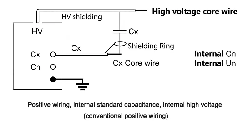
Wiring instructions:
- Insert the high-voltage cable into the instrument’s HV socket. Connect the large red clip to the high-voltage end of the test object, and leave the small black clip suspended or connect it to an appropriate shielding part.
- Insert the low-voltage CX test cable into the CX socket. Connect the red clip of the CX cable to the low-voltage end of the test object, and leave the black clip suspended or connect it to the shield terminal.
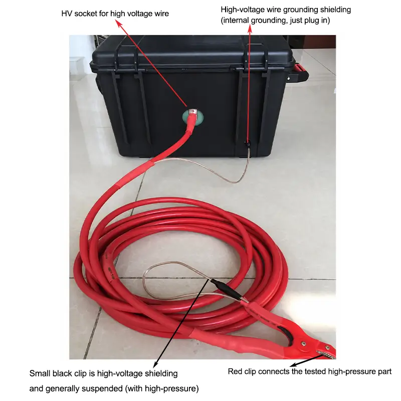
After connection, check that all clips are secure and avoid clamping onto paint, rust, or oxidation layers.
2. GST (Grounded Specimen Test)
GST is mainly used when one end of the tested equipment is permanently grounded and the conventional UST cannot be used. Examples include fixed bushings installed on transformers and equipment that cannot be detached from the ground on-site.
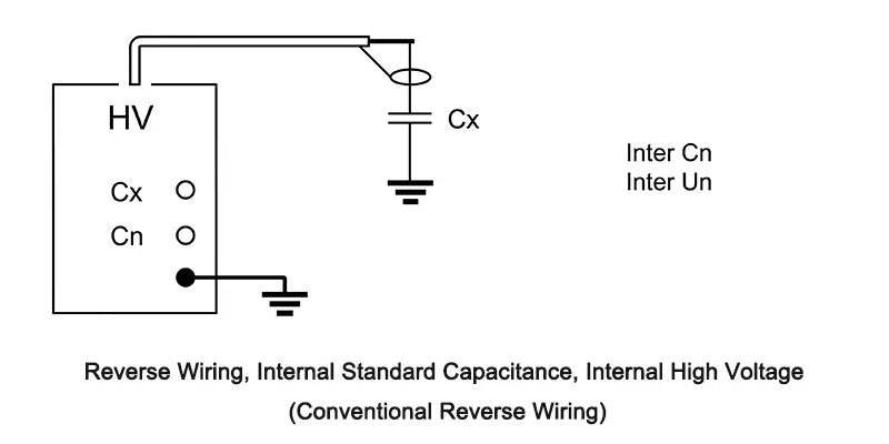
Wiring instructions:
- Insert the high-voltage cable into the HV socket. Connect the large red clip to the high-voltage end of the test object, and leave the small high-voltage clip suspended or connect it to a shielding device.
- The CX socket is usually left unconnected. The grounding status of the test object must match the selected GST mode.
For equipment like bushings and CVTs, GST is often used to measure the insulation parameters between the grounded end and the high-voltage end.
Step 7: Start Testing and Monitor the Voltage Increase
After confirming that no one is near the testing area, wiring is correct, and grounding is reliable, click “Start Test”.
The instrument will automatically execute:
- Automatic voltage increase;
- Specimen current collection;
- Calculation of capacitance and tanδ;
- Multi-frequency point measurement in dual-frequency mode;
- Display of test results.
During the test, closely monitor whether the output voltage and current are stable. If an overcurrent alarm occurs or the test object makes abnormal discharge noises, STOP the test immediately. Follow safety regulations to discharge and ground the equipment before inspecting it.
Step 8: Read, Store, and Export Data
Once the test is complete, you can perform the following actions on the results screen:
- Click “Store” to save the data;
- Input the data ID number;
- Click “Print” to output a paper copy of the test results;
- Use a USB drive to export historical data;
- Connect to a computer via the RS232 interface for data management.
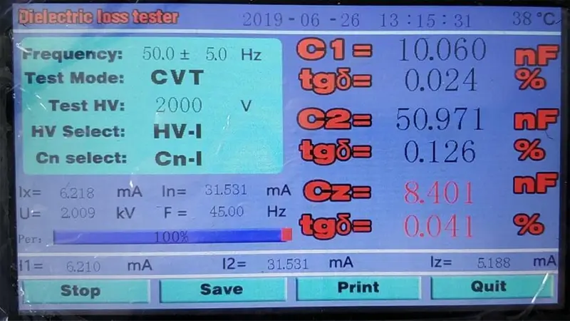
It is recommended to record the following information for each test:
- Substation or project name
- Name of tested equipment
- Equipment ID/Number
- Test date and environmental temperature/humidity
- Test voltage
- Test frequency
- Wiring mode
- Capacitance
- Tanδ value
- Test personnel
- Comparison with historical data
4 Rules to Improve On-site Data Reliability
- Wiring quality is more important than increasing voltage: Ensure clips are attached to clean metal surfaces. Never attach them to oxidized layers or painted surfaces.
- Always use dual-frequency in strong interference environments: Substations have heavy background power frequency interference. The dual-frequency algorithm is the most effective way to eliminate false measurement fluctuations.
- Maintain consistent testing conditions: When making historical longitudinal comparisons of the same equipment, try to keep the test voltage, wiring method, and temperature/humidity as consistent as possible.
- Keep high-voltage leads off the ground: Unshielded high-voltage test leads must be suspended in the air as much as possible to avoid additional loss errors caused by stray capacitance to ground.
Frequently Asked Questions (FAQ)
Q1: What potential hazards can high-voltage tan delta testing detect in equipment?
It is primarily used to detect overall moisture in the insulation systems of transformers and bushings, insulating oil degradation, internal void discharges, and structural insulation aging.
Q2: How do I quickly determine whether to use UST or GST based on on-site conditions?
The core principle is whether the low-voltage end of the test object is grounded. If the low end is completely insulated from the ground, prefer UST (it offers the highest accuracy). If the low end is permanently connected to the ground and cannot be detached, you must use GST.
Q3: Can a tan delta test completely replace an insulation resistance (Megger) test?
No. Insulation resistance mainly reflects penetrating insulation cracks and surface insulation resistance, while dielectric loss reflects the overall distributed capacitance and AC active power loss. The two methods complement each other.
Conclusion
High-voltage dielectric loss testing is a rigorous and precise preventive electrical test. From the initial power-off and discharge, surface cleaning, and securing dedicated grounding, to correctly matching UST/GST modes and selecting dual-frequency anti-interference settings, every functional detail directly determines the validity of the final insulation assessment.
Choosing a highly automated test instrument with strong anti-interference capabilities and comprehensive safety interlocks (such as the ZWJS101) can significantly reduce the impact of on-site wiring and complex electromagnetic environments on test results. This drastically cuts down outage maintenance time and provides solid data support for the safe and stable operation of critical power assets like transformers, instrument transformers, and bushings.
EXPERT GUIDANCE
Need Help Choosing the Right Testing Equipment?
High-Accuracy Tan Delta Testing Solutions
Whether you are selecting a highly reliable tan delta tester for a substation project or need professional technical wiring guidance when testing special equipment on-site (such as CVTs or capacitive bushings), our engineering technology team is always ready to provide comprehensive support.
Request Product Literature: Get the complete technical specifications for the ZWJS101.
Get an Exclusive Quote: Tell us your procurement needs and quantity to receive an official quote including shipping and delivery lead times.
One-on-One Technical Consultation: For anti-interference questions, special wiring needs, or difficult tan delta data encountered on-site, our senior high-voltage electrical engineers have the answers.
Customized Testing Solutions: We provide one-stop, bundled equipment solutions for substation high-voltage insulation testing.
Contact Us today, fill out your requirements, and our technical sales team will reach out to you within 24 hours!