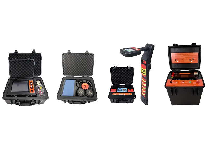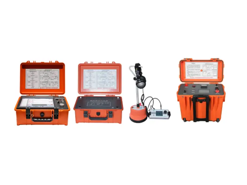
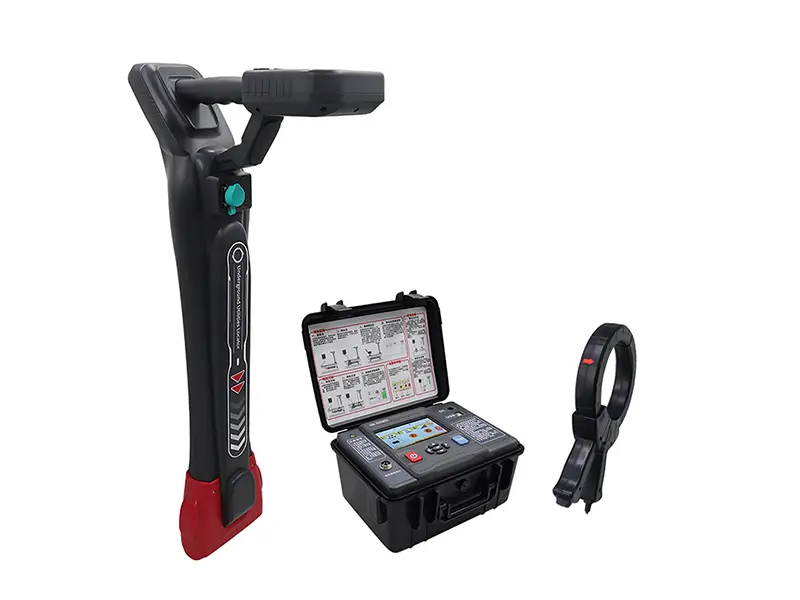
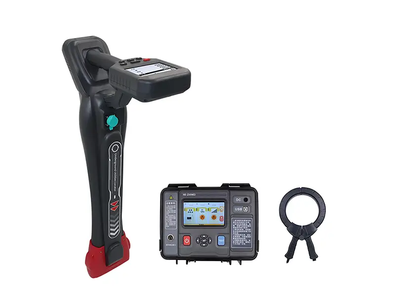
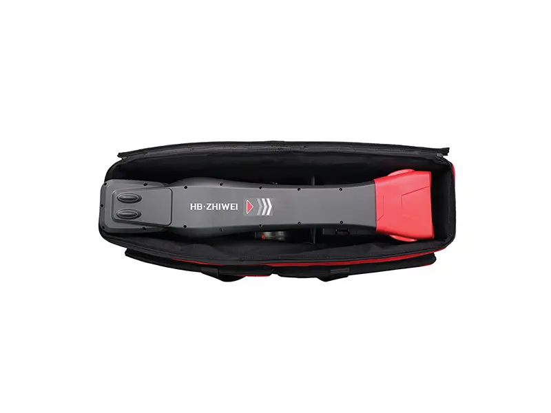
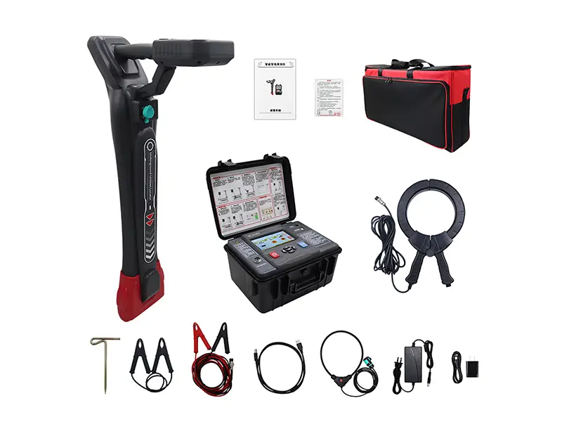
Underground Utilities Locator
The ZWS7080 is a comprehensive detection system strictly designed for tracing underground metal pipelines, uniquely identifying target cables (live or dead), and pinpointing sheath grounding faults.
It integrates a 15W high-voltage transmitter, a highly sensitive multi-antenna receiver, and an optional A-frame setup to deliver precise 20-meter depth mapping.
Product Overview
The ZWS7080 system supports Direct Connection, Caliper Coupling, and Induction signal transmission methods. It utilizes a 5-inch LCD transmitter and a 4.3-inch LCD receiver to map underground infrastructures across 11 active test frequencies.
Key Functions and Features:
1. Pipeline Path Detection: Offers three receiving modes (Wide Peak, Narrow Peak, Sound Valley) and three display interfaces (360° Wire Cruise, Classic Compass Positioning, Signal Distortion Measurement).
2. Target Cable Identification: Identifies a specific target cable (live or uncharged) from bundles of up to 20 cables using a flexible Rogowski coil (φ200mm).
3. Grounding Fault Locating: Integrates with an optional A-Frame to pinpoint low-resistance grounding faults and cable sheath damage using the step-voltage method.
4. Current Direction Determination: Measures phase and current direction at specific frequencies (640Hz to 3.20kHz) to isolate the target line and reject signals from adjacent parallel pipes.
5. Automated Depth & Current Measurement: Calculates underground depth (0 to 20 meters) and cable current in real-time. Supports manual validation via 45° Sound Valley and 80% Wide Peak methods.
6. Multiple Frequency Operations: Features 11 active frequencies (640Hz to 197kHz) and passive detection modes (50/60/250Hz power frequencies and various RF bands) for unpowered sweeps.
7. 15W Smart Transmitter: Outputs a maximum of 150Vpp direct voltage and 15W power (9 adjustable levels) with automatic real-time impedance matching and short-circuit protection.
Technical Details
| Receiver specifications | Receiver specifications2 |
|---|---|
| Function | Utility detection, cable identification, fault detection (optional) |
| Power | 8.4V large capacity rechargeable lithium battery |
| Input mode | Built-in receiving coil, flexible caliper, A-frame (optional function) |
| Receive frequency | Active detection frequency: 640Hz、1.28kHz、2.56kHz、3.20kHz、4.09kHz、8.19kHz、10.2kHz、32.7kHz、65.6kHz、81.9kHz、197kHz |
| Power frequency passive detection frequency:50Hz、60Hz、250Hz | |
| RF passive detection frequency band: the central frequency is divided into:32.7kHz、65.7kHz、81.9kHz、197kHz | |
| Utility detector modes | Wide peak, narrow peak, sound valley method |
| Utility detector display modes | Classic positioning mode, wire cruise mode, signal distortion measurement mode |
| Utility detection Scope of detection | Direct connection method: generally can reach the cable length of 0~20km. |
| Coupling method: generally can reach the length of the cable 0~10km. | |
| Induction method: suitable for cables with buried depth less than 2m. | |
| Measurement depth | 0-20m |
| Deep precision | ±5% (0-3m); ±10% (3m-20m) |
| Interference distance | Utility detection: >20m; Cable identification: >2~5m |
| Cable identification Range of detection | Direct connection: 0Ω~8kΩ (up to 20 km); Coupling method: 0Ω~1kΩ (up to 6 km) |
| Display | 4.3" LCD color touch screen |
| Size & Weight | 350mm*155mm*700mm; Around 2kg |
| Coil inner diameter | φ200mm (Customizable) |
| Withstand voltage | AC2000V/rms(Before the front and rear ends of the shell) |
| Suitable for safety regulations | IEC61010-1 CAT Ⅲ 600V,IEC61010-031,IEC61326,Pollution grade 2 |
| Transmitter specifications | Transmitter specifications2 |
|---|---|
| Function | Multiple frequency signal transmission modes |
| Power | 10.8V rechargeable lithium battery |
| Output method | Direct connection, caliper coupling, induction |
| Output frequency | 640Hz, 1.28kHz, 2.56kHz, 3.20kHz, 4.09kHz, 8.19kHz, 10.2kHz, 32.7kHz, 65.6kHz, 81.9kHz, 197kHz |
| Output mode | Automatic identification, according to different accessories |
| Output power | 15W max,The 9 gear adjustable |
| Impedance | Automatic real-time impedance matching and protection function |
| Direct output voltage | 150Vpp max |
| circuit protection | With overload and short-circuit protection S |
| Display | 5-inch LCD Color screen LCD |
| Size | Instrument: 320mm*275mm*145mm; clamp 297mm×194mm×39mm |
| Weight | Transmitter: ~3.85kg; Clamp: ~1.18kg |
| Launch clamp inner diameter | φ125mm |
| Length of transmitter clamp | 3m |
| P-wire | Red test line 3m, black test line 3m |
| Withstand voltage | AC 3700V/rms(Before the top surface and bottom surface of the instrument box) |
| Electromagnetic characteristics | IEC61326(EMC) |
| Suitable for safety regulations | IEC61010-1(CAT Ⅲ 300V、CAT IV 150V、Pollution grade 2) |
Model Selection Guide
| Feature | ZW5320 | ZW8320 |
|---|---|---|
| Max Output Current | 20A | 20A |
| Max Resistance Range | Up to 200Ω | Up to 25kΩ (Includes 10mA, <1mA steps) |
| 3-Phase Auto Test | Supported | Supported |
| Auto Degaussing | Supported | Supported |
| Magnetic Assist | Not available | Supported |
| Best Application | Standard distribution & medium power transformers. | Large power transformers requiring rapid LV winding tests. |
Recent Work
Parts List
| Item NO. | Max Current | Measuring Range | Main Features | Recommended Application |
|---|---|---|---|---|
| GDZR-10A | 10A | 100μΩ - 20KΩ | Portable, built-in discharge alarm | Small to medium distribution transformers |
| GDZR-20A | 20A | 10μΩ - 10KΩ | High-speed testing, heat dissipation | Medium-sized power transformers |
| GDZR-40A | 40A | 1μΩ - 2KΩ | Dual-channel measurement, high current | Large-scale power transformers |
| GDZR-40A | Three-Phase 10A | 100μΩ - 10KΩ | Three-phase simultaneous measurement | Yn-type transformers, time-saving |
Product Video
Discover how the ZWJD111E BDV Tester simplifies insulating oil diagnostics.

Certificate

Frequently Asked Questions
Contact our engineers for technical support and application guidance.
Use the built-in Current Direction Determination function. At frequencies between 640Hz and 3.20kHz, the receiver compares the current phase. A green tracking arrow pointing forward indicates the target pipeline, eliminating false readings from nearby lines.
Yes. The system supports Live Cable Identification using the Caliper Coupling method. You snap the transmitter clamp around the cable at the source, and use the flexible Rogowski receiver coil at the destination.
No. This kit locates paths, depth, and low-resistance sheath/grounding faults (using the A-frame). For high-resistance or flash-over faults, you need a high-voltage surge generator and a TDR fault locator (like our ZWT201 Cable Fault Testing System).
The device performs automated and manual depth measurements down to 20 meters, with an accuracy of ±5% for depths up to 3 meters.
Related Products