
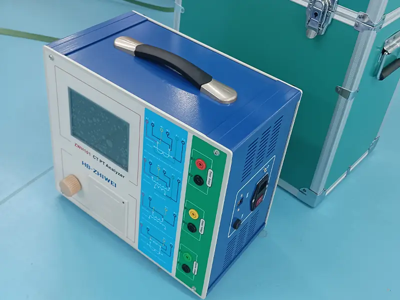
Instrument Transformers: Including Current Transformers (CT) and Voltage Transformers (PT/VT), they proportionally reduce dangerously high voltages and massive currents to standard, safe levels (such as 1A, 5A, or 100V/110V). These safe signals are then used by protection relays, billing meters, and SCADA control systems.
However, instrument transformers operate long-term under continuous thermal, mechanical, and high-voltage insulation stress. If hidden defects inside a CT or PT are not found in time, the consequences can be disastrous.
During severe short-circuit faults, protection relays may fail to operate (leading to switchgear explosions) because they cannot get the true current. Alternatively, they might falsely trip during normal grid switching (causing large-scale blackouts). Furthermore, even minor metering accuracy drift will cause huge financial losses for power companies over time.
A modern, multi-functional CT/PT Comprehensive Characteristics Analyzer is the ultimate diagnostic firewall for substations. By using advanced mathematical modeling and automated testing, high-end analyzers can accurately locate complex physical and electrical defects inside protection and metering transformers before a catastrophic failure occurs.
Core Technology Breakthrough: How the “Low-Frequency Method” Disrupts Traditional Testing
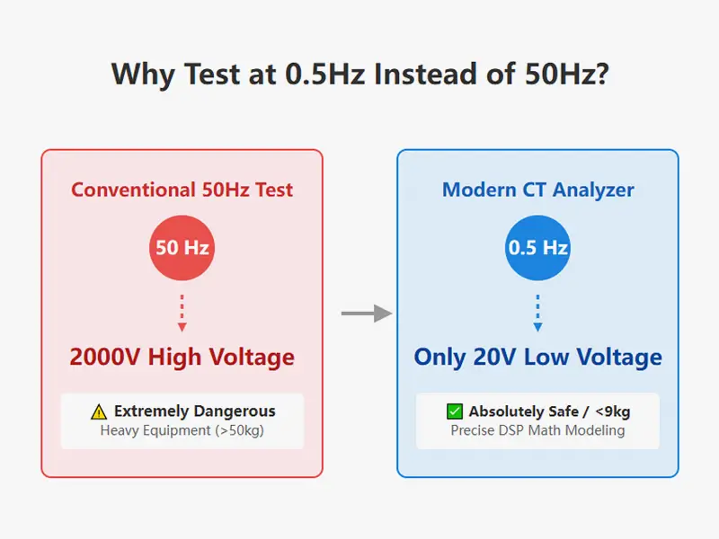
In the past, to test the excitation characteristics (finding the knee point voltage) of high-voltage protection CTs, engineers had to use bulky high-current generators and massive step-up transformers that output thousands of volts. This traditional method not only brought huge safety risks to on-site testers but also caused extreme thermal fatigue to the secondary windings.
Modern automated CT/PT analyzers completely eliminate these risks by using the low-frequency testing method (complying with IEC 60044-6 / GB 16847 standards).
The Underlying Physics of Low-Frequency Testing
According to the basic laws of electromagnetic induction, the AC voltage (V) applied across the CT secondary winding is proportional to the excitation current (I), excitation inductance (L), and test frequency (f):
V= I · Z= I · (2πfL)
From the formula, it is clear that to reach a specific saturation inductance (L) and excitation current (Ix) in the core, the required test voltage (Vx) is linearly proportional to the frequency (f).
At standard power frequency (f = 50 Hz), reaching the knee point might require a high voltage of 2000V.
If we lower the testing frequency to f = 5 Hz, reaching the exact same magnetic saturation state only requires 200V.
When the frequency drops to f = 0.5Hz, the required voltage sharply drops to just 20V.
By combining a high-performance Digital Signal Processor (DSP), ARM microcontroller, and low-frequency signal generation technology, modern analyzers can output very low voltages to accurately calculate the true excitation curve up to 45kV (and theoretically up to 65kV) at 50Hz/60Hz. This makes lab-grade diagnosis on portable devices a reality.
Key Fault Detection for Current Transformers (CT)
A comprehensive CT/PT analyzer can evaluate the core’s electromagnetic behavior and test the physical integrity of the copper windings. Here are the core defects the analyzer can detect on-site:
1. Core Saturation and Excitation Anomalies
When a short circuit happens in the grid, the primary current can surge to 20 to 40 times the rated value. If the CT core saturates too early, the secondary output current will heavily distort or even drop to zero, causing the failure of differential or overcurrent protection devices (known as the “relay blind spot”).
- Knee Point Voltage (Ek / Vk) and Current (Ik) Drift: The analyzer automatically finds the exact knee point “when a 10% increase in voltage causes a 50% increase in excitation current.” A drop in knee point voltage usually means aging silicon steel sheets in the core or inter-laminar short circuits.
- High Remanence Factor (Kr): High current shocks or sudden DC cut-offs can leave residual magnetism (remanence) in the core. If the remanence is too high (Kr > 10%), the CT will saturate instantly during the next fault. The analyzer accurately measures Kr and automatically performs a demagnetization cycle after testing.
- Transient Parameters (Ts, Lu, Kssc): For transient protection class CTs (like TPY, TPX, TPZ), the analyzer can calculate the secondary time constant (Ts), unsaturated inductance (Lu), and symmetrical short-circuit current factor (Kssc). This verifies the core’s ability to handle DC offsets during high-speed auto-reclosing (C-t1-O-tfr-C-t2-O).
2. Winding Resistance and Internal Turn-to-Turn Short Circuits
Even small turn-to-turn short circuits inside the secondary winding might not trigger the circuit breaker immediately, but they will rapidly reduce the CT’s load capacity and ratio accuracy over time.
- DC Winding Resistance Measurement (Rct): The analyzer uses high-precision 4-wire connections to completely eliminate test lead resistance interference. A high resistance indicates loose connections or oxidation; a low resistance directly exposes turn-to-turn short circuits caused by broken enamel insulation.
- Automatic Temperature Correction: Copper resistance changes with temperature. Advanced analyzers record the current ambient temperature (e.g., 25°C) and automatically correct the resistance value to the rated reference temperature of 75°C, ensuring the data meets international standards.
3. Ratio Error, Phase Error, and Polarity Reversal
- Ratio Error (ε): Even a 0.5% ratio drift on a metering CT can cause power companies to lose huge amounts of money in billing.
- Phase Displacement (Δφ): Phase errors measured in “minutes (min)” can seriously affect active/reactive power calculations and cause directional protection devices to make wrong judgments.
- Polarity Check: Wrong wiring during installation or maintenance can cause a 180-degree phase flip. The analyzer automatically determines if the CT has subtractive (-) or additive (+) polarity, preventing disastrous false operations of differential protection when the device is put into service.
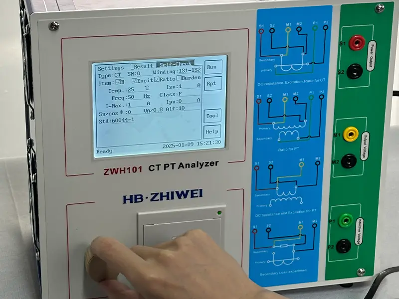
Fatal Risk Detection for Voltage Transformers (PT/VT)
A CT is a current source connected in series, while a PT is a voltage source connected in parallel to the high-voltage busbar. Therefore, PTs face completely different insulation and load challenges.
1. Insulation Aging and Dielectric Faults
The primary winding of a PT continuously bears phase-to-ground or phase-to-phase high-voltage stress, making it very prone to insulation fatigue.
- Excitation Characteristics and Core Loss Anomalies: Similar to CTs, the analyzer draws the excitation curve by applying voltage to the PT secondary winding. If it finds abnormally high excitation current at the rated voltage (100V/110V), or if the curve bends abnormally, it usually indicates localized core overheating, insulation degradation, or partial winding damage.
2. Secondary Load Mismatch and Overload
A PT can only guarantee its rated accuracy class (like Class 0.2 or 0.5) when connected to a specific range of secondary-side impedance (known as rated burden, VA).
- Secondary Burden Measurement: As substations are upgraded, engineers often add new microcomputer protection devices, power quality analyzers, or longer test cables to existing PT circuits. If the total impedance (Zb) exceeds the PT’s rated capacity, the secondary voltage will drop sharply.
- Power Factor (cosφ) Analysis: The analyzer (with the PT disconnected) injects a test signal directly into the secondary circuit to accurately measure the actual impedance (Zb) and power factor (cosφ). This ensures the connected devices will never overload the PT’s output.
Why is Predictive Maintenance Far Better Than Reactive Repair?
For instrument transformers, if a CT explodes due to long-term core saturation and overheating, the collateral damage to adjacent busbars and switchgears often costs hundreds of times more than the CT itself.
By introducing automated CT/PT analyzers to build regular predictive maintenance plans, substation operation and maintenance teams gain massive engineering and economic value:
- Auto-generated 5% and 10% Error Curves: No need for tedious manual calculations. Based on the tested excitation and resistance data, the analyzer directly plots the 10% and 5% error curves (M-Zb curves) on the screen. Engineers can instantly see if the existing secondary circuit impedance (Zb) is within a safe range at a given short-circuit multiplier (M).
- Drastically Reduced Downtime: Modern devices offer one-click automated testing. They can finish resistance, excitation, ratio, and polarity tests for multi-winding CTs within 2 minutes, reducing power outage times for acceptance and routine checks by 70%.
- Data Traceability and Compliance: The device can store 2000 sets of test data. Users can generate Word reports complying with national and international standards (GB 20840.1, IEC 60044-6, IEC 61869-2/3, C57.13) with one click via PC software.
Selection Guide: The Hardcore Strength of ZHIWEI ZWH101 Comprehensive Characteristics Analyzer
When selecting on-site test equipment, power margin, test accuracy, and environmental adaptability are the three core indicators. The Baoding ZHIWEI ZWH101 Variable Frequency Instrument Transformer Comprehensive Characteristics Analyzer is built for the harshest substation environments, giving you true lab-grade accuracy.
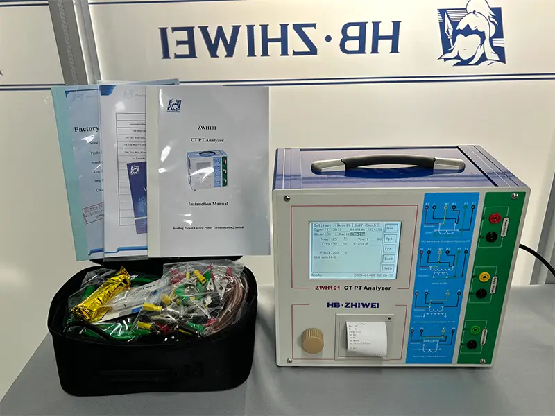
1. Real Factory Calibration Data: Uncompromising 0.2% Accuracy
Putting aside empty marketing words, ZHIWEI speaks with real national-level calibration data. We randomly selected a newly produced ZWH101 unit (Serial Number: 25011562, Calibration Date: Jan 7, 2025) and recorded its actual calibration data in a constant temperature and humidity lab (25°C, 60% RH). (Note: The entire calibration used national traceable standard instruments, including a UTD2102CEL oscilloscope, a 34401A high-precision multimeter, and LZZBJ6-16, TPY Class 2500:1 standard current transformers.)
Table 1: ZWH101 Factory Calibration Record (SN: 25011562)
| Test Item | Standard Reference Value | ZWH101 Measurement | Error Rate | Conclusion |
|---|---|---|---|---|
| AC Voltage Output | 10.0000V | 9.9999V | -0.001% | PASS |
| 50.0000V | 49.9298V | -0.140% | PASS | |
| 70.0000V | 70.0100V | 0.014% | PASS | |
| AC Current Output | 0.1000A | 0.0998A | -0.200% | PASS |
| 1.0000A | 0.9982A | -0.180% | PASS | |
| 2.0000A | 1.9967A | -0.165% | PASS | |
| Winding Resistance (1 Ω) | 0.9909 Ω (Bridge measurement) | 0.9903 Ω | -0.060% | PASS |
| Secondary Burden Test (1 VA) | 0.9902 Ω (Standard load) | 0.9910 VA | 0.080% | PASS |
| CT Ratio & Error (Subtractive) | 600:1 (Class M Metering) | 600:0.9993 | -0.070% | PASS |
| 200:5 (Class P Protection) | 200:4.998 | -0.040% | PASS | |
| 3000:5 (Class P Protection) | 3000:5.002 | 0.040% | PASS | |
| 2500:1 (Class TPY Transient) | 2500:0.9996 | -0.040% | PASS |
The calibration report clearly proves: Whether for protection class (P), metering class (M), or transient class (TPY), the ZWH101’s ratio error is far below ±0.1%, completely exceeding international standard requirements.
2. Technological Superiority: ZWH101 vs. European Industry Benchmarks
Many imported test devices are limited by very small internal power supplies, often struggling when facing high-impedance loads on-site. The ZWH101 has completely upgraded its underlying architecture:
Table 2: Tech Comparison: ZHIWEI ZWH101 vs. Mainstream European Benchmarks (e.g., Omicron-level products)
| Core Tech Indicator | ZHIWEI ZWH101 | Imported Benchmark Devices | On-Site Engineering Advantages |
|---|---|---|---|
| Independent Power Output | 2100VA (Peak 3000VA) | 400VA (Peak 1500VA) | Easily drives high-impedance, long-cable CT/PT secondary circuits. The device will not overheat, crash, or stop testing due to overload. |
| Size, Weight, and Power Ratio | Under 9kg total (while providing 2100VA high power) | Approx. 8kg total (can only provide 400VA low power) | Solves the technical pain point that lightweight and high power are traditionally mutually exclusive. |
| Max Output Voltage/Current | 0-180Vrms / 12A (Peak 18A) | 0-120Vrms / 5A (Peak 15A) | Higher voltage/current ceiling. Can more accurately excite and measure transformers with high knee point voltages. |
| Max Supported Knee Voltage | Up to 65kV | Up to 40kV | Powerful low-frequency algorithm fully covers 500kV and above extra-high voltage GIS and transformer bushing CTs. |
| Transformer Class Coverage | Standard full support for P, TPY, Metering, PR, PX, TPS, TPX, TPZ | Supports base classes like P, TPY, Metering (British PR/PX usually requires optional expensive software or tedious setups) | Perfectly compatible with special transient classes globally (including British Standard BS PR/PX classes). Fully equipped out of the box with no hidden fees or upgrades. |
| User Interface Logic | Rotary knob + Full English graphical UI | Traditional keyboard input / Heavily relies on external PC | Allows single-handed operation even while wearing insulated gloves in -10°C cold, vastly improving the on-site experience. |
| Case and Maintenance | Modular aluminum alloy case design | Complex internal structure; customers cannot disassemble | Tough and bump-resistant. In case of sudden failure, customers can quickly replace modules on-site without returning it to the factory. |
Frequently Asked Questions (FAQ)
Q1: How often should I test instrument transformers using a CT/PT analyzer?
For new substations, Factory/Site Acceptance Tests before putting them into service are mandatory. For daily predictive maintenance, we recommend comprehensive routine tests every 1 to 3 years for critical transmission-level transformers (110kV and above).
Also, if the grid just experienced an extremely severe short-circuit fault, it is highly recommended to run a test with the analyzer immediately before re-energizing to check for high residual magnetism (Kr) and insulation damage.
Q2: Can the analyzer really detect turn-to-turn short circuits inside the transformer?
Absolutely. The analyzer locks onto turn-to-turn shorts by catching two abnormal signals: First, the 4-wire DC winding resistance (Rct) test result will be significantly lower than the factory nameplate value or similar connected devices. Second, on the excitation curve, the knee point voltage (Vk) will collapse abnormally, and the excitation current will show massive spikes at very low voltages.
Q3: What is CT saturation, and why is testing the knee point voltage so important?
CT saturation happens when primary short-circuit currents rapidly increase, causing the magnetic flux density inside the core to exceed its linear magnetization range.
When saturation occurs, the CT’s excitation impedance drops sharply, turning most of the primary current into excitation current. This severely distorts the secondary output current so it cannot truly reflect the primary current. Consequently, protection relays fail to operate because they can’t get valid fault current signals.
Accurately testing the knee point voltage (Ek) and the Accuracy Limit Factor (ALF) verifies if the CT has enough anti-saturation margin to face extreme short-circuit shocks up to 20kA or more. This ensures the CT maintains linear current transmission, allowing protection relays to safely and precisely isolate faults.
EXPERT GUIDANCE
Need Help Choosing the Right Testing Equipment?
Conclusion
In modern power systems, from minor metering drift to extreme protection failures, any potential fault in instrument transformers can trigger immeasurable chain reactions. Therefore, fully shifting substation maintenance from “passive response” to “proactive prediction” is an inevitable trend.
Excellent maintenance starts with accurate diagnosis
An excellent testing terminal should be an engineer’s most solid technical backup when checking for hidden hazards. With its unique low-frequency algorithm, class-leading 2100VA power margin, and traceable 0.2% production test accuracy, the ZHIWEI ZWH101 perfectly handles the harshest on-site testing environments, leaving no hidden defects in your instrument transformers anywhere to hide.
Say goodbye to blind troubleshooting and build truly reliable health records for your substations. Feel free to contact us:
✉️ sales001@zhiweielectric.com | 💬 WhatsApp: +86-13833237336