
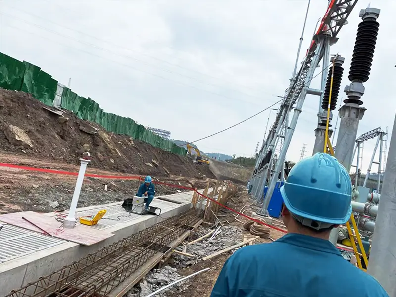
High-voltage insulation resistance testing, often referred to as megohmmeter or Megger testing, is the most fundamental and vital diagnostic method for evaluating the insulation health of power transformers, generators, XLPE cables, and high-voltage switchgear.
According to international standards such as IEEE 43-2013 (Recommended Practice for Testing Insulation Resistance of Electric Machinery), IEEE C57.12.90 (Test Code for Liquid-Immersed Distribution, Power, and Regulating Transformers), and IEC 60076-1:
Relying solely on a single 60-second spot reading can be highly misleading. Accurate modern diagnostics require a combined approach: Dielectric Absorption Ratio (DAR), Polarization Index (PI), leakage current monitoring, and stepped ramp tests. Powered by a high-voltage digital megohmmeter capable of a short-circuit current of ≥ 5mA, this approach cuts through on-site electromagnetic noise to clearly identify whether the issue is moisture ingress, surface contamination, or deep mechanical degradation.
Written by the engineering team at HB ZHIWEI Electric Power, this article breaks down the physical currents at work during testing, explains key diagnostic thresholds, and outlines a standardized testing workflow aligned with international factory inspection standards.
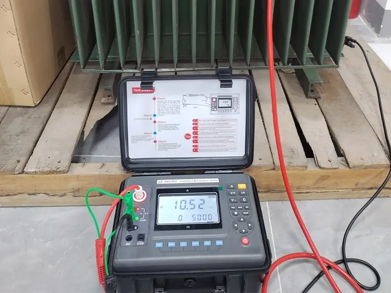
The Physics of Insulation Resistance: Why a Single Spot Reading Can Mislead
When you apply a constant DC high voltage (such as 2.5kV, 5kV, 10kV, or 15kV) between a high-voltage conductor and ground, the total current flowing through the insulation, Itotal(t), is not constant. Instead, it is the dynamic sum of three distinct current components over time:
Itotal(t) = Ic(t) + Ia(t) + Ig
- Geometric Capacitive Charging Current (Ic): Drops exponentially to zero within seconds as the asset charges up like a capacitor.
- Dielectric Absorption / Polarization Current (Ia): Decays gradually over minutes to tens of minutes as molecular dipoles reorient with the electric field.
- Steady-State Conduction / Leakage Current (Ig): Stays constant over time, reflecting internal material degradation and surface leakage.
Common Field Pitfalls:
Capacitive Charging Bias: Long cables and large transformers often have capacitances reaching several microfarads (μF). In the first 10 to 20 seconds of testing, the measured current is dominated by the capacitive charging current (Ic). Calculating resistance at this stage (R = U / I) yields a deceptively low reading.
Temperature and Humidity Sensitivity: For every 10°C increase in temperature, the volume resistivity of insulating materials drops by roughly half. Furthermore, humid ambient air forms a thin condensation film across porcelain bushings, creating significant surface leakage.
Bottom line: Never determine the condition of an asset from a single 1-minute resistance reading (in MΩ or GΩ). You must filter out environmental influences and rely on dynamic diagnostic ratios like PI and DAR.
Deep Dive into Key Diagnostic Metrics: DAR, PI, and the Ramp Test
(1) Dielectric Absorption Ratio (DAR)
DAR is primarily used to evaluate moisture in lower-capacitance assets (such as circuit breakers, voltage transformers, and small-to-medium motors) or materials where absorption stabilizes quickly.
Calculation:
DAR = R60s / R15s or DAR = R60s / R30s
Diagnostic Criteria (based on IEEE 43 guidelines):
- DAR ≥ 1.4: Excellent insulation (dry and clean).
- 1.0 ≤ DAR < 1.25: Acceptable, but monitor for early moisture ingress.
- DAR < 1.0: Severe moisture contamination or conductive defects. Do not place in service!
(2) Polarization Index (PI)
For large power transformers, EHV XLPE cables, and generator stator windings, dielectric relaxation takes a long time. The absorption current (Ia) will not fully settle within one minute. In these applications, the 10-minute to 1-minute resistance ratio is used:
Calculation:
PI = R10min / R1min
Diagnostic Value:
When insulation absorbs moisture, free conductive ions multiply rapidly. The steady leakage current (Ig) becomes far greater than the absorption current (Ia). Because Ig is dominant and flat, R10min barely climbs above R1min, dragging the overall ratio close to 1.0.
| Measured PI | Insulation Condition | Recommended Action |
|---|---|---|
| PI ≥ 4.0 | Excellent: Completely dry, full molecular polarization | Safe for service; record as baseline data |
| 2.0 ≤ PI < 4.0 | Good: Normal aging, fully acceptable | Maintain regular preventive testing schedule |
| 1.0 ≤ PI < 2.0 | Warning: Early moisture ingress or oil degradation | Shorten test intervals; run oil tests for moisture and DGA |
| PI < 1.0 | Poor: Severe moisture ingress or carbonized conductive tracks | Do not energize; perform hot-oil circulation drying immediately |
Important Note: If an asset suffers from localized physical damage (such as a clear mechanical puncture) under dry conditions, its PI can sometimes still read within normal limits. Insulation resistance and PI testing should always be paired with Partial Discharge (PD) Testing and Turns Ratio Testing to obtain a complete assessment of insulation health.
(3) Ramp Voltage Test: Non-Destructive Breakdown Diagnostics
Conventional step-voltage tests apply the full rated test voltage immediately. If the insulation contains deep micro-cracks, this sudden surge can trigger an immediate flashover, causing irreversible damage.
Test Mechanism: The megohmmeter ramps the voltage smoothly and linearly in increments (for example, stepping up by 10% of the target voltage: 1.5kV → 3.0kV → … → 15kV).
Diagnostic Principle:
- Dry, healthy insulation maintains a linear current response as voltage increases.
- If the current suddenly spikes non-linearly or resistance drops sharply as the voltage steps up, microscopic avalanche breakdown has started at that specific field strength. The test can be halted immediately, identifying the critical insulation threshold before an arc permanently damages the equipment.
Solving Field Errors: How to Use the Guard Terminal Correctly
During rainy seasons or in coastal substations with high salt fog, test readings can drop dramatically—for instance, a transformer’s reading might plunge from dozens of GΩ down to a few dozen MΩ. This is usually not caused by internal insulation breakdown, but by moisture and conductive contaminants on the porcelain bushing surface creating an external leakage path to ground.
How Guarding Works:
The common mistake: Connecting only the LINE and EARTH terminals. In this setup, surface leakage flows directly through the instrument’s measurement circuit, adding to the internal current and causing the displayed resistance to read hundreds of times lower than it actually is.
Correct procedure:
Wrap a clean, bare copper wire tightly around the surface of the asset (such as around the bushing skirt or the stripped section of a cable sheath) to form a guard ring;
Clip the tester’s green GUARD lead securely onto this ring;
The guard circuit diverts surface leakage directly back to the source, bypassing the internal measuring circuit. The instrument then measures only the true volume insulation resistance of the material itself.
Note: Always connect the GUARD terminal when measuring high-impedance insulation in the 10 GΩ to TΩ range.
Why Short-Circuit Output Current (≥ 6mA) Is Critical for Mid-to-Large Power Assets
Many budget handheld testers provide a short-circuit current of only 1mA to 2mA. When connected to long 35kV/110kV cables or massive power transformers, these low-power meters often yield unstable readings or lock up entirely.
Large Capacitance Charging Dynamics:
The charging rate is governed by the transient formula:
dV / dt = Isc / C
For a cable with an equivalent capacitance of C = 2μF at a test voltage of V = 10kV:
- With a 1mA tester:
Charging time t = (2 × 10-6 F × 10,000 V) / 0.001 A = 20 s.
During the crucial first 15 seconds, the voltage cannot even reach the rated test level, making the DAR measurement invalid. - With a high-power tester delivering ≥ 6mA (such as the ZWS3045):
Charging time drops to under 3 s. The test voltage stabilizes almost instantly, allowing the tester to capture the true dielectric polarization curve from the very first second.
Interference Suppression:
High-voltage substations carry strong electromagnetic fields from nearby energized equipment. High output power combined with dedicated hardware noise-filtering algorithms suppresses induced AC voltages, ensuring stable readings down into the microampere and picoampere (pA) ranges.
Standardized Field Testing and Safe Discharge Procedures
Testing at voltages up to 15kV carries serious shock hazards, and capacitive equipment stores lethal amounts of energy. Always follow these standard operating steps:
- Step 1: De-energize the equipment, verify zero voltage, and attach safety grounds.
- Step 2: Check for induced AC/DC voltage (use the tester’s pre-check circuit to confirm residual voltage is ≤ 0V).
- Step 3: Connect test leads in strict order: Earth (Black) to the equipment frame ground; Guard (Green) to the anti-tracking ring; and High Voltage Line (Red) to the conductor last.
- Step 4: Ensure personnel stand back at a safe distance, then begin the test (the instrument will emit continuous warning beeps and flash its indicators).
- Step 5: Critical safety step: Perform active capacitive discharge before touching anything.
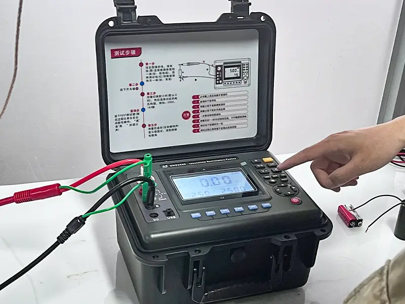
Ensuring Accuracy at the Source: Factory Inspection and Traceability
High-voltage testing instruments demand strict measurement accuracy and reliable operator protection. Every unit leaving the production line must pass comprehensive testing under simulated extreme conditions.
HB ZHIWEI strictly complies with IEC 61010-1 safety requirements and GB/T 1094 power equipment standards. Before delivery, every ZWS3045 insulation resistance tester undergoes power-on tests, acoustic checks, structural torque verification, and full-parameter calibration to guarantee 100% data repeatability in the field.
Frequently Asked Questions (FAQ)
Q1: Why must a megohmmeter have a short-circuit current of ≥ 6mA when testing large transformers or long cables?
High-capacitance assets draw a heavy charging current when voltage is first applied. Testers with low output currents (1mA to 2mA) charge slowly and take tens of seconds to reach the target voltage, invalidating the 15-second DAR measurement. A short-circuit current of ≥ 6mA brings the voltage up to target levels in milliseconds, capturing an accurate polarization curve from the first second while cutting through strong electromagnetic interference in substations.
Q2: Why does a PI close to 1.0 on modern dry-type epoxy transformers or XLPE cables not necessarily mean the insulation has failed?
The traditional benchmark of PI ≥ 2.0 was established for older oil-paper and asphalt-mica insulation, both of which absorb moisture readily. Modern solvent-free epoxy resins and high-purity XLPE materials undergo polarization very quickly, with absorption current decaying to near zero within tens of seconds.
By the time readings are taken at 1 minute and 10 minutes, the current consists almost entirely of a tiny, flat leakage current, naturally resulting in an R10min / R1min ratio around 1.0 to 1.3.
As long as the absolute insulation resistance is exceptionally high (in the hundreds of GΩ or TΩ range), a low PI is completely normal on these materials and does not indicate moisture.
Q3: After the tester’s internal discharge completes, why can a long cable or large transformer still build up a dangerous residual charge?
This occurs because of dielectric absorption recovery voltage. While the tester’s internal discharge resistor quickly drains the surface capacitive charge, deep polarized dipoles release their trapped energy much more slowly.
If external grounding is removed too quickly, the conductor can rebound to thousands of volts of static charge within minutes. Standard safety guidelines require discharging the asset for at least 2 to 4 times the test duration, and keeping a physical discharge stick grounded to the conductor before disconnecting any test leads.
EXPERT GUIDANCE
Need Help Choosing the Right Testing Equipment?
Conclusion
High-voltage insulation resistance testing is far more than just reading numbers off a display. It is a systematic diagnostic process that examines polarization behavior, moisture ingress, and dielectric withstand limits under high stress.
By understanding polarization index trends, using the GUARD terminal to bypass surface leakage, and using high-current (≥ 6mA) testers with ramp testing functions, maintenance teams can reliably catch insulation defects long before catastrophic flashovers occur.
Technical Support and Product Recommendations
If your maintenance team is dealing with slow charging on large transformers, erratic readings in damp conditions, or difficult cable diagnostics, consider the industrial-grade HB ZHIWEI ZWS3045 Insulation Resistance Tester. It features an adjustable output up to 15kV, a strong ≥ 6mA short-circuit current, automated PI / DAR / Ramp routines, and hardware noise filtering paired with active discharge protection.
Contact our engineering team today for technical manuals, factory inspection reports, or guidance on selecting the right setup for your site.