
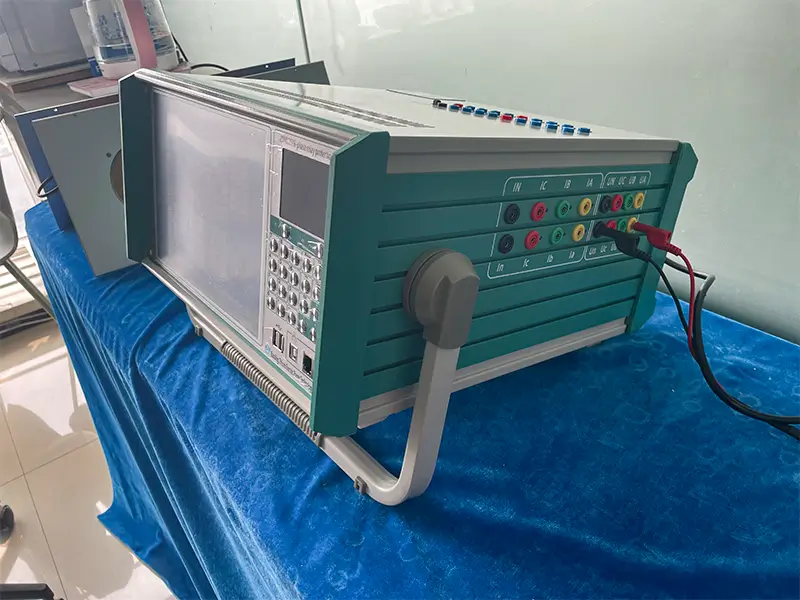
In the operation and maintenance of modern power systems and substation secondary circuits, relay protection devices act as the last line of defense to prevent large-scale power outages and protect primary equipment (transformers, generators, transmission lines). To verify protection logic and operating times, engineers rely on secondary injection testing equipment for routine maintenance and handover tests of relays.
As substations become more automated, traditional single-phase or three-phase testers often fall short when dealing with three-winding transformer differential protection, complex automatic transfer switch (ATS) logic, and microcomputer line protection. The 6-phase microcomputer relay protection tester has now become the standard tool for modern substation secondary testing.
This article will guide you through the technical advantages, core testing scenarios (differential / distance / ATS / harmonics), and hardware architecture of 6-phase relay protection testers. We will also share actual calibration accuracy data from authoritative third-party testing labs, helping your team choose the most cost-effective equipment.
Why Do Substation Secondary Tests Need “6-Phase” Voltage and Current Outputs?
Many new engineers in the industry often ask: “Three-phase testers can already output 3-phase voltage and current. Why do we need to upgrade to 6-phase?”
The key difference lies in the ability to synchronously inject and vector-synthesize three-phase signals at two (or multiple) ends at once, without the need for frequent rewiring.
Core Physical Advantages
1. High-Current Parallel Capability: A single phase can output 0~30A. When testing zero-sequence stages or instantaneous overcurrent protection that require large currents, 6 current phases can be paralleled in-phase to reach up to 180A (with a maximum output power of 1000VA). This easily meets various heavy-load testing requirements.
2. Simultaneous Injection on Both Transformer Sides: It allows for true simultaneous injection on the high-voltage side (IA, IB, IC) and the low-voltage side (Ia, Ib, Ic), accurately verifying waveform phase differences and balance coefficients.
3. Line Voltage and Independent DC Auxiliary Power: It can directly output 0~240V AC line voltage and 0~±320V DC voltage. It also provides an independent 110V/220V dedicated DC auxiliary power supply to directly power the protection device under test.
Core Application Scenarios and Advanced Testing Modules
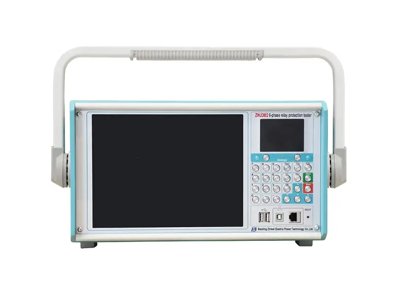
Taking the ZWJD802 Smart 6-Phase Relay Protection Tester as an example, its architecture is based on DSP+FPGA (16-bit DAC, high-density sine waves at 2000 points per cycle) and high-fidelity linear amplifiers. It provides the following complete secondary testing solutions:
(1) Transformer Differential Protection
Transformer differential protection is easily affected by wiring groups (like Y/D-11), CT ratio balance coefficients, and inrush currents.
Ratio Braking Boundary Search: The software automatically calculates the high and low voltage side balance coefficients (K1, K2). By entering the formulas for operating current (Id) and braking current (Ir), it automatically searches for the ratio braking characteristic curve.
Harmonic Braking Characteristic Test: It superimposes 2nd to 20th harmonics onto the fundamental current. This accurately measures the harmonic blocking threshold (usually a 15%~20% superimposed amount) of the protection device during transformer no-load closing (inrush current).
(2) Impedance Distance and Zero-Sequence Protection
For 110kV and above transmission line protection:
Impedance Step Testing: Automatically verifies the operating impedance and time limits of zones Z1, Z2, Z3, and Z4. The system supports automatic scanning at set impedance multiples like 0.7x, 0.95x, 1.05x, and 1.1x to verify the logical clearance time.
Zero-Sequence Overcurrent: Supports various ground fault simulations (A-N, B-N, C-N). Users can automatically input the zero-sequence compensation coefficient KX (e.g., 0.67) to accurately measure direction and time limits under specific pulses.
(3) Standby Automatic Switching (ATS)
ATS logic involves active standby, hidden standby, switch position status, and multi-bus loss-of-voltage detection. The ZWJD802 offers a dedicated “State Series” and ATS testing module:
It captures circuit breaker trip/close statuses in real-time through 8 pairs of binary inputs (supporting dry contacts and 0~250V DC active potentials).
It can sequentially simulate the entire logic process: “Normal operation -> Main power loss and disconnection -> ATS action and closing -> ATS closes onto a faulted line and trips again immediately.”
(4) Fault Replay
Supports direct import of IEEE COMTRADE data files generated by power system fault recorders. The tester accurately recreates the exact voltage and current transient waveforms from actual grid faults, which is extremely useful for analyzing complex tripping events or the response behavior of microcomputer protection relays.
Authoritative Third-Party Calibration Data
As a high-precision calibration tool, the tester’s own output accuracy directly determines the reliability of your maintenance conclusions. Below is the actual calibration data of the ZWJD802 6-phase tester developed by Baoding Zhiwei, tested by an authoritative national-level metrology laboratory.
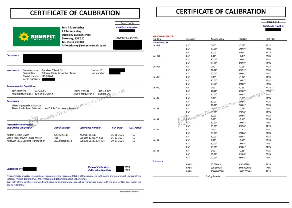
Note: Privacy information has been safely removed. Please do not screenshot or use without authorization.
1) 6-Phase AC Voltage (50Hz) Accuracy Check
| Applied Standard Voltage (V) | Measured Voltage Reading (UA) | Tolerance Range | Calibration Result |
|---|---|---|---|
| 2.000V | 2.002V | ±9mV | PASS |
| 10.00V | 10.00V | ±25mV | PASS |
| 50.00V | 50.01V | ±105mV | PASS |
| 120.00V | 120.06V | ±245mV | PASS |
Note: The 6-phase voltages UA, UB, UC, Ua, Ub, Uc show excellent linearity across all channels, with full-scale errors as low as under 0.05%.
2) 6-Phase AC Current (50Hz) Accuracy Check
| Applied Standard Current (A) | Measured Reading (IA) | Measured Reading (IB) | Tolerance Range | Calibration Result |
|---|---|---|---|---|
| 0.500A | 0.497A | 0.497A | ±6mA | PASS |
| 5.000A | 4.998A | 5.000A | ±15mA | PASS |
| 10.00A | 10.00A | 10.00A | ±25mA | PASS |
| 30.00A | 30.01A | 30.02A | ±65mA | PASS |
3) Ultra-Fine Resolution for Phase Angle and Frequency
Phase Accuracy Check (Under 100V, 5A conditions):
Standard 0.00° → Measured -0.03° ~ -0.09° (Industry tolerance: ±0.5°). This performance far exceeds industry standards.
Standard 90.00° → Measured 89.97° ~ 90.01° (PASS).
Frequency Accuracy Check (0.001Hz High Resolution):
Standard 50.0000Hz → Measured 49.9992Hz;
Standard 1000.0000Hz (High Frequency) → Measured 1000.0050Hz (Error is only 0.005Hz).
Field Troubleshooting and Safety Guidelines
When using a microcomputer relay protection tester, following the correct operating procedures will greatly reduce the risk of equipment damage and ensure personnel safety:
Safety Warnings and Wiring Sequence
1. Grounding First: Before turning on the power or connecting test leads, you must solidly connect the dedicated ground terminal on the back panel to the substation’s ground grid (0-ohm grounding).
2. No Reverse Feed: It is strictly forbidden to feed external AC or DC power back into the voltage/current output jacks of the tester!
3. About Sparks: It is normal to see a slight spark when connecting the current circuit (there is about 20V of floating voltage in the current circuit). The spark will disappear once the circuit is closed. To completely avoid sparks, turn off the amplifier power before plugging or unplugging test leads.
Common Field Anomalies and Diagnostic Tips
| Phenomenon Description | Possible Causes | Solution |
|---|---|---|
| Software shows “Device not connected” (USB communication error) | 1. The knob is not turned to the “Industrial PC” side. 2. The DSP control board is frozen. | 1. Check the USB selection switch on the panel. 2. Press the red RST reset button on the panel and wait 5 seconds for it to reconnect. |
| The panel current open-circuit light (Red) turns on | The tested phase current circuit is disconnected or has very high impedance. | Check if the test clamps are clipping onto painted surfaces; check the continuity of the current wires. |
| The panel voltage short-circuit light (Red) alarms | A short circuit occurred on the corresponding voltage phase, or it was pulled down by an external low impedance. | Turn off the amplifier power, remove the short circuit point on the test wires, wait 20 seconds, and turn the power back on to recover. |
| Inaccurate operating time due to relay chatter | Mechanical contacts or electromagnetic relays experience chattering the moment they act. | In the software interface, increase the “Contact Jitter Delay” from the default 10ms to 20~50ms. |
Frequently Asked Questions (FAQ)
Q1: Can a 3-phase relay tester measure a three-winding transformer differential by using secondary conversion methods?
Yes, it can, but it is extremely tedious and prone to errors. A 3-phase tester can only test one phase or part of the windings on both sides at a time. This requires manual rewiring multiple times and manual calculation of phase differences. With the ZWJD802 6-phase tester, you can inject 6 phases simultaneously with a single wiring setup, greatly reducing substation maintenance time.
Q2: What is the purpose of the “dual-frequency” test (e.g., 45Hz / 55Hz) in the software?
In operating high-voltage substations, there is very strong 50Hz spatial electromagnetic interference. The frequency conversion test injects signals on both sides of 50Hz (like 45Hz and 55Hz). By using the digital Fourier transform (DFT) algorithm, it effectively filters out the 50Hz interference signals, ensuring highly repeatable test results.
Q3: Why doesn’t this device require opening the chassis and adjusting potentiometers for accuracy calibration?
The ZWJD802 uses advanced Software Self-Calibration technology. Engineers simply enter the actual voltage and current values measured by a high-precision standard meter (like the Agilent 3458A) into the software’s calibration menu. The system automatically calculates the coefficients and writes them into the flash memory, eliminating the aging and drifting issues common with traditional mechanical potentiometers.
Summary
From basic overcurrent relays to complex impedance distance, transformer differential, ATS logic, and harmonic analysis, the ZWJD802 Smart 6-Phase Relay Protection Tester is built to handle it all.
With its 180A high-current parallel capability, 0.2% full-channel accuracy, and an embedded Windows industrial PC, it delivers an all-in-one, high-efficiency secondary testing solution for grid contractors and maintenance teams worldwide.
As a National High-Tech Enterprise with over a decade of R&D expertise, Zhiwei Electric has designed this tester to deliver laboratory-grade accuracy that consistently outperforms standard equipment on the market, helping you identify hazards early and ensure the longevity of your core power assets.
EXPERT GUIDANCE
Need Help Choosing the Right Testing Equipment?
Partner with Zhiwei Electric for Your Power Testing Needs
At Baoding Zhiwei Electric Power Technology Co., Ltd., we provide complete and reliable power testing solutions. Guided by our core values of Long-Termism and Integrity, and backed by a strict “3-Stage Quality Control” process (Raw Materials, Production, and Final Product), our equipment is trusted by clients across Southeast Asia, the Middle East, Europe, and the Americas for applications in power utilities, oil & gas, railways, and transformer manufacturing.
Beyond relay protection testers, we offer 7 comprehensive product series, including transformer testing equipment, insulating oil analysis, battery testers, SF6 gas testing, and cable fault diagnostics.
Ready to upgrade your secondary testing efficiency?
Whether you need a customized testing solution, detailed technical data sheets, or a competitive quote, our engineering and sales teams are ready to assist you.
- Email: sales001@zhiweielectric.com
- WhatsApp: +86 13833237336
Contact us today to get a free comprehensive product brochure and see how Zhiwei Electric can safeguard your critical infrastructure!