
I. Introduction: Pain Points and Challenges in On-site Testing
In substation commissioning and power system maintenance, ensuring that circuit breakers and protection relays trip instantly and accurately during faults is key to grid safety. To verify this process, engineers usually need to perform current injection tests.
However, on-site testing often comes with huge challenges. Traditional high-current generators mostly use bulky linear transformers, making the equipment weigh tens of kilograms and hard to move around in complex substations. At the same time, the devices easily overheat during continuous high-current output, causing test interruptions. Worse still, the poor current output accuracy of low-end equipment directly leads to distorted test results for the relay’s action time.
To solve these problems, we first need to deeply understand the core principles of primary current injection testing and master scientific equipment evaluation standards.
II. Core Definition and Principles of Primary Current Injection Testing
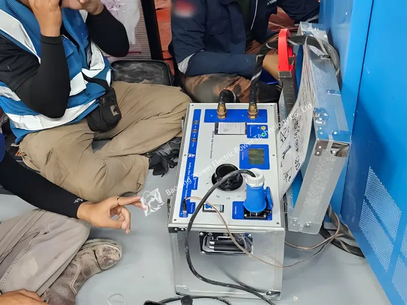
Primary current injection testing refers to injecting a large current (usually ranging from 100A to thousands of amperes) directly into the primary circuit of power equipment.
Unlike testing just the protection relay itself, primary injection testing verifies the integrity of the entire protection loop.
The large current flows through current transformers (CTs), circuit breaker contacts, connecting cables, and protection relays. This test truly simulates extreme conditions when the grid experiences short circuits or overloads, thereby identifying hidden faults such as reversed CT polarity, loose cables, CT saturation, or mechanical jamming of circuit breakers.
III. Primary vs. Secondary Injection: Core Differences Explained
To help you make the right decisions during procurement and on-site testing, the table below compares the two most common testing methods in power systems in detail:
| Comparison Metric | Primary Current Injection Testing | Secondary Current Injection Testing |
|---|---|---|
| Injection Point | Primary circuit (High-voltage side main conductor/busbar) | Secondary circuit (Input terminal of protection relay) |
| Test Current Magnitude | Very large (100A to 1000A+) | Small (Usually 1A or 5A) |
| Test Coverage | Full loop: Covers CTs, secondary wiring, relays, and circuit breaker mechanical parts | Partial: Only tests the logic and action of the protection relay itself |
| Equipment Requirements | Requires a high-power, high-capacity high current generator | Requires a high-accuracy, small current/voltage output tester |
| Typical Applications | Final acceptance testing (FAT/SAT) before commissioning a new substation | Routine maintenance and daily calibration of relays |
To dive deeper into standard commissioning workflows and find out whether you should perform primary or secondary injection first, read our comprehensive guide on the [Primary vs. Secondary Injection Tests]
IV. Procurement Guide: How to Evaluate Professional Equipment
When buying a primary current generator or protection relay tester, rather than just looking at the maximum current value on the nameplate, you should focus on the following three hidden metrics that determine on-site efficiency:
1. Portability and Underlying Technology:
Say no to traditional linear regulator designs. You should choose equipment that uses advanced switching power supply technology. This technology ensures a large power output of over 1.5KW while shrinking the device’s size and weight to a level that one person can easily carry.
2. Accuracy and Zero Drift Control:
At very low ranges (such as under no load), poor-quality devices will show tens of millivolts of zero drift. An excellent tester should have a voltage/current measurement accuracy of 0.5% ±1 digit. It should also have a high-precision digital stopwatch (with an accuracy of ±0.0001 s) to precisely capture the contact action time.
3. Multi-function Expandability:
Does the device have special terminals designed for high internal resistance relays (like GL type inverse time relays)? Can it simultaneously handle AC and DC output (AC 150A / DC 20A)?
V. ZHIWEI Solution: A Safe Tester Built for On-site Pain Points
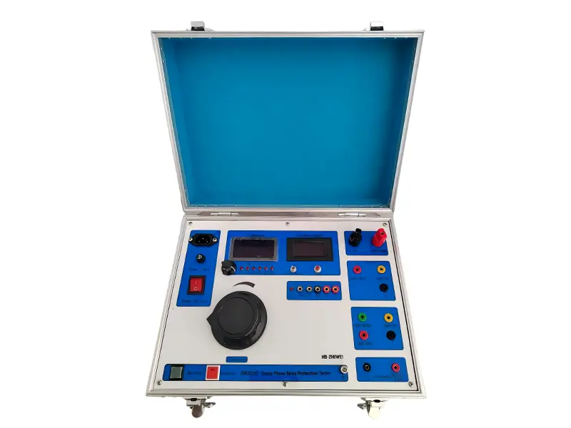
Based on the strict engineering requirements mentioned above, ZHIWEI developed the ZWJD101 single-phase protection relay tester. It scientifically integrates a current generator, a digital electrical stopwatch, and a standard voltage/current meter into one unit, perfectly solving on-site pain points.
1. Backed by Real Data: Uncompromising Engineering Accuracy
In industrial testing, data is the only universal language. According to actual records from factory calibration certificates sampled by ZHIWEI, the ZWJD101 shows amazing linear accuracy:
(Batch number: 20241119093, Testing environment: 15-30 °C, Humidity 45-75% RH)
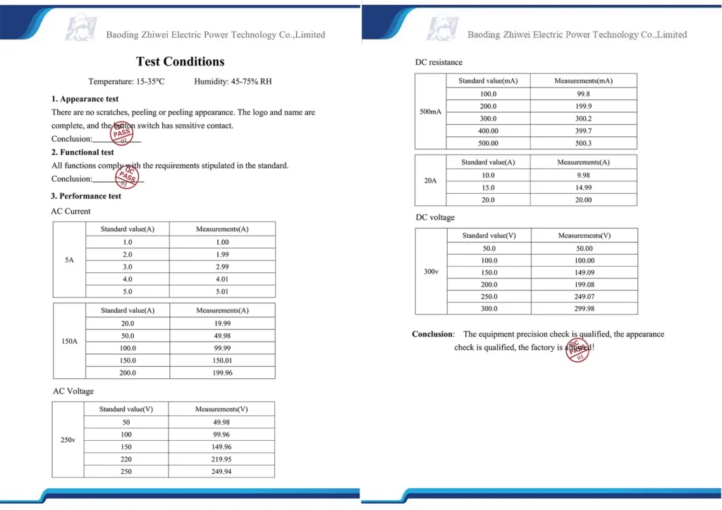
- High current output (Primary injection simulation): When the standard value is 150.0A, the actual measured output is 150.01A.
- Small current output (Secondary injection): When the standard value is 5.0A, the actual measured output is 5.01A.
- AC voltage output: When the standard value is 250V, the actual measured output is 249.94V.
This 0.5% level accuracy, covering extremely large ranges, ensures that engineers always get the most authentic reference data, whether it’s for action values, return values, or impact tests.
2. Solving Transport and Heating Pain Points
The ZWJD101 uses an advanced switching power supply architecture inside, which massively cuts down the weight of the device. Its maximum output power reaches 1.5KW, supporting a fully adjustable AC high current of 0~150A.
To tackle the heating issues common with high currents, the device is optimized for short-time, close-range measurements. It is equipped with dual protections (a fuse and an automatic air switch) to ensure the safety of both personnel and the equipment.
3. Designed for Complex Relays
For inverse-time relays with high internal resistance, such as the GL and LL types, the ZWJD101 panel includes a specially designed 45A AC current output terminal with a 20V voltage. This makes it incredibly easy to start induction elements without needing extra adapters, successfully completing the action current and time tests for quick-break elements.
VI. Frequently Asked Questions (FAQ)
1. Can the ZWJD101 be used for primary current injection testing in substations?
The AC current output range of the ZWJD101 is 0~150A. For main busbar tests that require extremely high current (like over 1000A), a generator with a larger capacity is required.
However, for lightweight primary tests under 150A, low-voltage distribution testing, and all secondary circuit injections, the ZWJD101 is your go-to portable choice.
2. Why does the DC ammeter on the instrument jump slightly when there is no load?
This is a normal “Zero Drift” phenomenon found in highly sensitive electronic instruments. The ZWJD101 manual clearly states that a fluctuation of tens of millivolts under no load is a standard baseline shift for the internal sensors. Once connected to a load for an actual test, this drift is completely suppressed and absolutely does not affect the final 0.5% testing accuracy.
3. How do I measure the return time of a relay?
The ZWJD101 has a built-in 8-digit digital stopwatch (0~99.99s). At the exact moment you cut the power output (by pressing the Stop button), the system automatically starts timing. When the normally open/normally closed contacts of the relay reset, the stopwatch stops, and the displayed value is the highly accurate return time (accuracy +/- 0.0001s).
EXPERT GUIDANCE
Need Help Choosing the Right Testing Equipment?
VII. Conclusion
Primary current injection testing is the last line of defense to keep power assets safe. Choosing test equipment means more than just buying parameters; it’s about buying on-site mobility, data accuracy, and operational safety.
By replacing heavy, traditional linear devices with the ZWJD101 tester—which leverages switching power supply technology and is backed by real calibration data—your team will significantly boost testing efficiency for substation FAT/SAT and routine maintenance.
Need detailed technical specs for the ZWJD101 or want a sample of the full factory calibration report? [Click here] to contact the ZHIWEI technical support team, or simply send an email to: sales001@zhiweielectric.com