
As core equipment in the power system, the operational stability of transformers directly determines the quality of the power grid’s supply.
The tap changer, being the key component for regulating the transformer’s output voltage, is frequently subjected to switching operations or on-load conditions, making it susceptible to faults such as contact wear, poor connections, and insulation aging.
Therefore, performing regular measurements on tap changers is a crucial measure for promptly identifying potential issues, preventing equipment damage, and avoiding power grid accidents.
The Necessity of Tap Changer Measurement
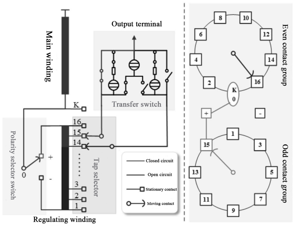
The primary function of a tap changer is to adjust the transformer’s output voltage by changing the winding turns ratio, adapting to load variations and voltage fluctuations in the power grid. During long-term operation, tap changers are prone to performance degradation due to the following factors:
Mechanical Wear: Frequent switching leads to oxidation, ablation, or wear on contact surfaces, increasing contact resistance and causing localized overheating during operation.
Insulation Aging: Internal insulation components of the switch can experience reduced insulation performance due to temperature, humidity, and electric fields, potentially leading to ground or phase-to-phase short circuits.
Oil Contamination: If the switch seal is compromised, impurities from the transformer oil can enter the switch interior, accelerating contact wear and insulation deterioration.
Operating Mechanism Failure: Jamming or loosening of mechanical transmission parts can lead to incorrect tap positions, causing voltage regulation to fail.
Through scientific measurement, these hidden dangers can be detected in advance, preventing transformer outages caused by tap changer failures and even averting large-scale power blackouts.
Common Measurement Items and Methods
Tap changer measurement should be based on its structural characteristics and fault types.
| Item | Test Equipment | Description |
|---|---|---|
| DC Resistance Measurement | DC Resistance Tester | Evaluate the contact quality of the tap changer contacts |
| Insulation Resistance Measurement | Insulation Resistance Tester | Evaluate insulation performance to prevent short circuits caused by insulation breakdown |
| Tap Position Verification | DC Resistance Tester | Verify the accuracy of the tap changer’s actual position |
| Contact Voltage Drop Measurement | On-load Tap-changer Tester | Evaluate dynamic contact performance |
The common measurement items and operating methods are as follows:
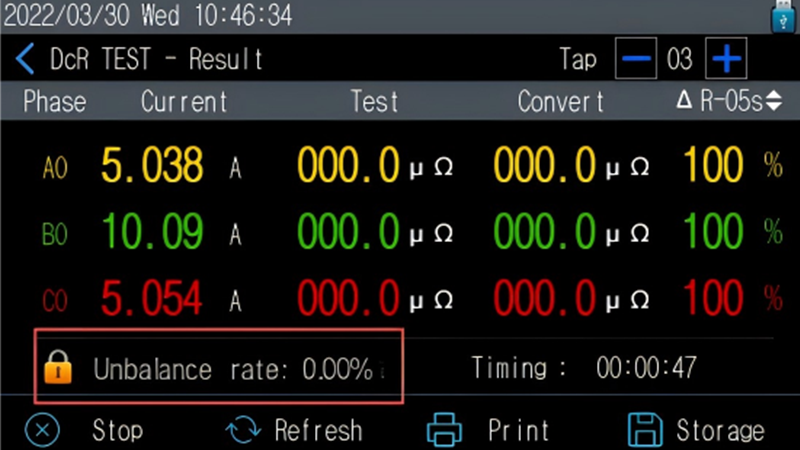
1. DC Resistance Measurement: Assessing Contact Status

DC resistance measurement is the most direct method for evaluating the contact quality of a tap changer. The core task is to detect the DC resistance value of the winding at each tap position and its deviation to determine if poor contact exists.
Measurement Principle: Based on Ohm’s Law, a constant DC voltage is applied across the winding, and the resistance is calculated by measuring the current (R=UIR=IU). The use of a DC signal eliminates interference from the winding’s inductance on the measurement results.
Key Operational Points:
1) Before measurement, the transformer must be taken out of service, de-energized, and the windings fully discharged (for at least 5 minutes) to prevent residual charge from affecting the data.
2) Use a double-arm bridge or a dedicated transformer DC resistance tester with an accuracy meeting the requirement of 0.1% to 0.5%. Avoid using standard multimeters due to their large error margin.
3) Measure the DC resistance at all tap positions, repeating the measurement 2-3 times at each position and taking the average to reduce random errors.
Acceptance Criteria: The deviation of DC resistance at the same tap position compared to historical data should not exceed ±2%. The resistance deviation between different tap positions should not exceed ±1%. If these limits are exceeded, investigate potential issues like contact oxidation, looseness, or winding faults.
2. Insulation Resistance Measurement: Evaluating Insulation Performance
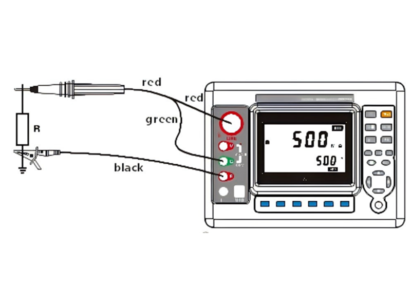
ZW1310 Insulation Resistance Tester
Insulation resistance measurement is used to check the condition of internal insulation components (such as insulating cylinders and rods) and the insulation to ground, preventing short circuits caused by insulation breakdown.
Measurement Principle: An insulation resistance tester applies a high DC voltage of 500V or 2500V to measure the leakage current through the insulation layer, calculating the insulation resistance (R=U/I). A higher resistance value indicates better insulation performance.
Key Operational Points:
1) Before measurement, clean oil stains and dust from the switch surface to prevent surface leakage current from affecting the data.
2) Measure the insulation resistance between “tap changer – ground,” “tap changer – winding,” and between different tap terminals. For each measurement point, hold the voltage steady for 1 minute before taking a reading.
3) The ambient humidity should be controlled below 75%. If humidity is high, drying measures should be taken to prevent moisture from causing a low insulation resistance reading.
Acceptance Criteria: For transformers with a voltage rating of 10kV and below, the tap changer insulation resistance must be at least 100MΩ. For 35kV and above, it should not be less than 250MΩ. The value should not show a significant decrease compared to historical data (deviation not exceeding 30%). Otherwise, an insulation oil dielectric strength test or disassembly inspection is required.
3. Tap Position Verification: Ensuring Regulation Accuracy
An incorrect tap position can cause excessive deviation in the transformer’s output voltage and may even lead to winding overvoltage. Therefore, it is necessary to periodically verify that the actual position of the tap changer matches the indication on the operating mechanism.
Measurement Methods:
Mechanical Verification: Manually operate the tap changer, record the “tap position” indicated by the operating mechanism, and simultaneously observe the actual position of the moving contact through the transformer tank’s observation window (or with an endoscope) to confirm they are consistent.
Electrical Verification: In conjunction with DC resistance measurement data, if the resistance value at a certain tap position is suddenly abnormal (e.g., a sharp increase), it may indicate that the moving contact is not fully engaged at that position. The operating mechanism linkage or contact position may need adjustment.
Acceptance Criteria: The “indicated position” and “actual position” must correspond perfectly for all taps, with no misalignment or jamming. The contact switching process should be smooth without noticeable sticking.
4. Contact Voltage Drop Measurement: Supplementary Assessment of Contact Quality
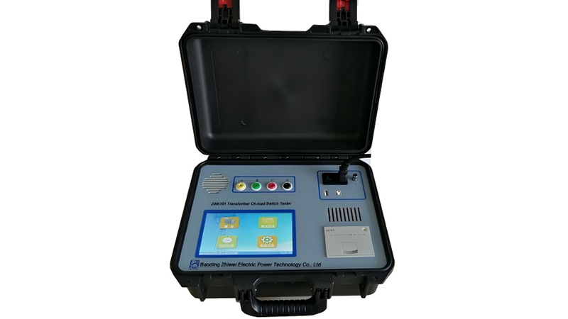
ZWK101 On-load Tap-changer Tester
For on-load tap changers (OLTCs), it is also necessary to measure the contact voltage drop to evaluate dynamic contact performance.
Measurement Principle: While the switch is carrying its rated current, use a millivoltmeter to measure the voltage drop across the contacts (Udrop=I×Rcontact). A smaller voltage drop indicates better contact.
Key Operational Points: Measurements should be taken in real-time during the switching process to record the maximum contact voltage drop, avoiding data deviation caused by heating during steady-state operation.
Acceptance Criteria: The contact voltage drop for copper contacts should not exceed 50mV, and for silver contacts, it should not exceed 20mV. If these values are exceeded, the contacts need to be polished or the contact assembly replaced.

Precautions During Measurement
- Safety Protection: Before measurement, hang “Equipment Under Maintenance, Do Not Close Switch” signs. Personnel must wear insulating gloves and shoes and use insulated tools to prevent electric shock.
- Equipment Status Confirmation: Ensure the transformer oil level is normal with no leaks, and the tap changer operating mechanism is free of rust or jamming to prevent secondary faults during measurement.
- Data Recording and Comparison: Record the ambient temperature, humidity, oil temperature, and the model of the measuring instrument. Compare the current data with historical data (e.g., factory test results, previous maintenance data) to identify potential faults through trend analysis.
- Handling Anomalies: If measurement data exceeds limits, first rule out external factors like instrument error or improper operation. Then, systematically investigate internal faults. If necessary, contact the manufacturer for a disassembly inspection. Never operate equipment with a known fault.
Summary
As the voltage regulation hub of the transformer, the performance of the tap changer directly affects equipment safety and grid stability.
Through core measurement projects such as DC resistance, insulation resistance, and tap position verification, a comprehensive understanding of the tap changer’s contact quality, insulation performance, and mechanical characteristics can be obtained, allowing for timely detection and elimination of hidden dangers.
In practice, it is essential to strictly follow measurement standards and focus on comparative data analysis to ensure that every measurement provides an effective guarantee for the reliable operation of the transformer, thus building the “first line of defense” for the safe and stable operation of the power grid.

Secure Your Grid’s Future: Take Proactive Control Today
The health of your transformer tap changers is not just a maintenance item—it’s the bedrock of your operational reliability. Waiting for a failure is a risk that can lead to catastrophic outages and staggering financial losses. A proactive, data-driven measurement strategy is your most powerful tool for ensuring uninterrupted service and extending asset life.
Don’t leave the stability of your power network to chance. Click here to discover our state-of-the-art diagnostic solutions or schedule a consultation with our power system experts to fortify your maintenance program and protect your critical infrastructure.


