
Localized overheating and arc faults caused by high-resistance connections are among the primary causes of power system fires and equipment damage.
As a specialized tool designed to detect these minute defects, the Loop Resistance Tester can accurately capture micro-ohm level resistance anomalies, building a solid line of defense for the safe operation of power grids and industrial equipment.
With deep expertise in the power testing field, ZHIWEI has become a key force in safeguarding grid safety through its high-precision, high-stability loop resistance testing equipment.
What is a Loop Resistance Tester?
Definition and Core Functions: Precise Measurement of Micro-Ohm Level Resistance
A Loop Resistance Tester (also known as Contact Resistance Tester or Micro-Ohmmeter) is a precision instrument utilizing advanced measurement technology specifically designed to measure the total resistance within a closed current loop.
Its core capability lies in accurately capturing resistance values ranging from micro-ohms (μΩ) to milli-ohms (mΩ).
Measurement targets encompass the combined resistance of conductive components, connection points, and conductors themselves, making it widely adaptable for low-resistance detection scenarios in power systems and industrial equipment to ensure reliable and accurate test results.
Loop Resistance vs. Contact Resistance: Clarifying Terminology Overlap
From a testing scenario perspective, although the names differ, their core applications highly overlap:
– Loop Resistance: Refers to the total resistance of all conductive parts in a complete current loop (such as the closed loop formed by main breaker contacts, busbars, and connecting wires).
– Contact Resistance: Focuses on the local resistance at connection points (such as joints, welds, and terminals) and is a key component of loop resistance.
In actual inspections, both require precise micro-ohm level measurement to identify defects; thus, they are often viewed as different expressions of the same testing requirement.
Why Is It Necessary to Perform a Loop Impedance Test?
Preventing Overheating and Equipment Failure: The Potential Risk of the I2R Thermal Effect
According to the principle of the I2R thermal effect, excessive resistance in a circuit leads to significant heat accumulation when current passes through. If contact resistance exceeds standards due to oxidation or loose bolts, it causes localized overheating and contact melting. In severe cases, it can trigger arc faults, directly damaging core equipment like high-voltage circuit breakers and switchgear, resulting in widespread power outages or safety accidents.
Compliance with IEC/IEEE Standards: Ensuring Compliance and Safety
Loop resistance testing is a mandatory requirement for power equipment inspection and must comply with international and industry standards such as IEC 62271-100 and DL/T845.4-2004. Standardized testing verifies the quality of equipment installation and maintenance, ensuring the power system meets safe operation specifications and avoiding equipment failure or O&M risks caused by non-compliance.
How Loop Resistance Testers Work?
Limitations of Multimeters: Two-Wire Method Failure at Low Resistance
Ordinary multimeters utilize a two-wire measurement method, where the resistance of the test leads is added to the measurement of the device under test. In micro-ohm scenarios, this lead resistance dominates the reading, causing significant data distortion and making precise detection impossible.
Deep Dive into the Four-Wire Kelvin Method: Eliminating Lead Resistance Interference
The core technology of a loop resistance tester is the Four-Wire Kelvin measurement method, which eliminates testing errors by separating the current lines (C lines) from the voltage lines (P lines):
– Current Lines: Output a constant high current (e.g., 50A, 100A) to the circuit under test, ensuring penetration of surface oxide films to reveal the true resistance.
– Voltage Lines: Only collect the voltage drop across the test points and do not carry the test current, avoiding the influence of lead resistance on the measurement result.
This separated design enables the instrument to accurately capture micro-ohm level resistance differences and is the key technology for low-resistance measurement.
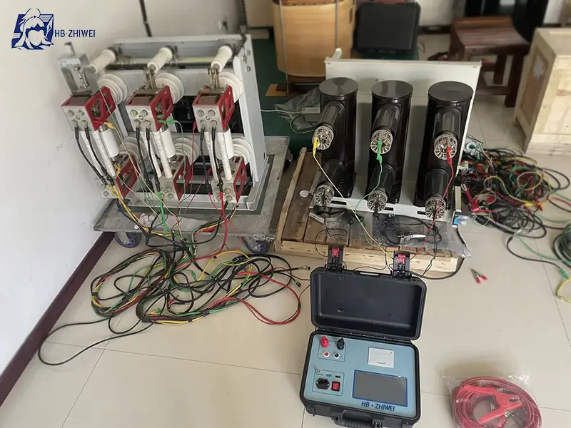
Application Fields of Loop Resistance Testers
High-Voltage Circuit Breakers: Detect main contact resistance to prevent overheating faults caused by contact aging or oxidation.
Switchgear Busbars: Troubleshoot resistance anomalies at busbar connection points and branches to safeguard power transmission efficiency.
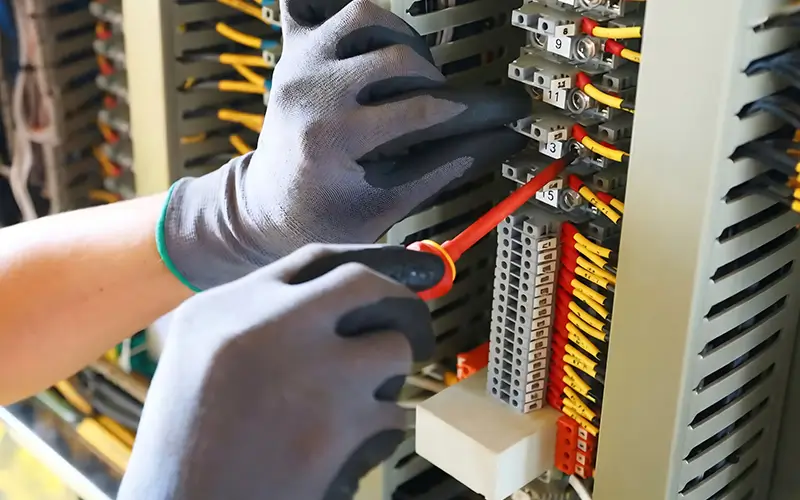
Cable Joints and Welding Points: Verify the connection quality of crimped joints and welds to avoid sub-standard resistance caused by poor connections.

How to Use a Loop Resistance Tester (Step-by-Step Guide)
1. Grounding and Safety: Disconnect all power sources, ground the test equipment, and verify there is no voltage to prevent electric shock or equipment damage.
2. Connect Current and Voltage Clamps: Using the four-wire connection method, clip the current clamps (C clamps) to both ends of the loop under test, and place the voltage clamps (P clamps) on the inner side of the test points, ensuring good contact.
3. Set Test Current: Select the test current according to standard requirements (e.g., 100A complies with IEC standards and is sufficient to break through oxide films).
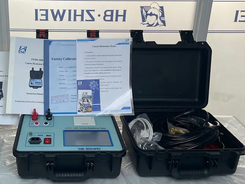
4. Read and Save Results: After starting the test, read the data via the instrument display and use the storage function to save results, supporting subsequent queries and report generation.
Buying Guide: Key Features to Consider
| Key Feature | Selection Points | ZHIWEI Advantage |
|---|---|---|
| Current Output | 50A (Basic), 100A (Mainstream Standard), 200A (High Requirement). Must match the test object. | Supports 50-200A adjustable constant current output, meeting precise testing needs across different scenarios. |
| Stability & Duty Cycle | Must be capable of continuous operation without overheating shutdowns. | Uses smart power management technology to ensure continuous measurement without overheating, offering superior stability. |
| Resolution & Range | Resolution should reach 0.1μΩ; Range covering 0~100mΩ (50A) / 0~50mΩ (100A). | Highest resolution of 0.1μΩ, with a wide range suitable for micro-ohm to milli-ohm measurements, ensuring precise data. |
| Data Storage & Output | Support for data storage, report generation, and multi-interface transmission. | Built-in storage for 1000 data sets, equipped with Bluetooth, RS232, and USB interfaces. Integrated panel micro-printer for real-time report printing. |
| Safety & Operation | Must have protections for over-temperature, over-current, and reverse potential; easy to operate. | Multiple safety protection functions, 7-inch high-brightness touchscreen; user-friendly interface. |
FAQ of Loop Resistance Testers
Q1: Why does the test current need to be at least 100A?
A: According to IEC standards, a high current of 100A is required to break through oxide films and oil films on contact surfaces. This avoids the influence of false contact resistance, ensuring the measurement results are authentic and reliable.
Q2: Can an ordinary multimeter measure contact resistance?
A: No. Multimeters lack sufficient resolution, and their two-wire measurement method cannot eliminate lead resistance interference, making them unable to accurately capture micro-ohm level resistance, resulting in significant errors.
Q3: How often should loop resistance be tested?
A: Testing is typically performed during new equipment commissioning and after maintenance. For routine O&M, it is recommended to test annually to track equipment aging and wear trends.
Q4: How is the “acceptable value” for loop resistance determined?
A: Refer to the equipment manufacturer’s manual. Generally, core equipment like high-voltage circuit breakers requires resistance appropriate to the type (usually <50-100 micro-ohms) and should show no significant anomalies when compared to identical equipment or historical data.
Q5: Can I use a Contact Resistance Tester instead?
A: Yes. The core technology and application scenarios for both highly overlap. Aside from the naming difference, both are used for low-resistance detection of connection points and loops.
Q6: Does temperature affect micro-ohm level measurement? Is correction needed?
A: Yes, the impact is significant. Metal resistance increases as temperature rises. It is necessary to record the ambient temperature during testing and correct the data based on the temperature coefficient of the equipment material to ensure accuracy.
Elevate Your Safety Standards with ZHIWEI
The Loop Resistance Tester is the “invisible guardian” of power system safety operations. Its precise micro-ohm level measurement capabilities allow for the early detection of equipment connection defects, preventing overheating faults and safety risks.
ZHIWEI Loop Resistance Testers, centered on the Four-Wire Kelvin method, combine high stability, portability, and rich data processing functions. They fully comply with IEC/DL standards and are adapted to multi-scenario testing needs such as high-voltage circuit breakers, switchgear, and cable joints.
Choosing ZHIWEI means choosing professional power testing protection
If you need a customized testing solution based on specific application scenarios (such as substations, industrial enterprises, or construction sites), or wish to learn more about product parameters and practical cases, please feel free to consult our technical team at any time.


