
A frequency sweep test, formally known as Sweep Frequency Response Analysis (SFRA), is a highly sensitive, non-destructive diagnostic method for power transformers. It can detect latent mechanical faults that conventional electrical tests (like turns ratio or insulation resistance tests) cannot find—including winding deformation, core displacement, and loss of clamping pressure.
By injecting a low-voltage AC signal across a wide frequency band into the transformer and comparing the resulting “fingerprint” curve with baseline data, engineers can assess the integrity of its internal structure without detanking (opening the transformer tank). It is a critical tool for ensuring grid reliability and asset management.
A Deeper Look into Sweep Frequency Response Analysis (SFRA)
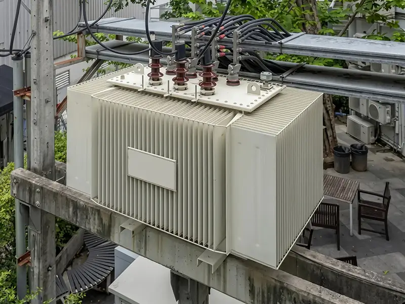
Power transformers are the backbone of the electrical grid, yet conventional electrical tests often fail to provide insight into the health of their internal mechanical structures. When a transformer is subjected to severe short-circuit faults, rough transportation, or external forces like earthquakes, its windings and core can sustain minor physical damage. If these hidden issues are not detected in time, they can eventually lead to catastrophic equipment failure.
SFRA technology successfully fills this gap by translating the transformer’s physical geometry into precisely measurable electrical characteristics. Internally, every transformer constitutes a complex and unique distributed RLC network composed of resistance (R), inductance (L), and capacitance (C).
This network is strictly determined by the transformer’s physical design: the distance between winding turns, the precise position of the core, and the tightness of the clamping structures.
This gives the transformer a unique “electrical fingerprint” that is directly intertwined with its mechanical condition. Once physical damage occurs (such as winding buckling or core shifting), the internal RLC parameters change, causing a shift in its frequency response characteristics. SFRA precisely diagnoses these hidden faults by capturing and analyzing these minute changes.
The Science Behind SFRA:
The total impedance (Z) of the transformer’s RLC network varies with the frequency (f) of the injected signal, following fundamental principles of electrical physics.
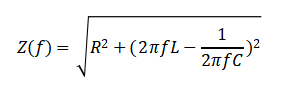
The inductance (L) and capacitance (C) in the formula are strictly determined by the transformer’s physical geometry. Even a shift of just 1-2 millimeters in winding position can alter these parameters, directly affecting the signal’s transfer function, H(f)=Vout/Vin.
SFRA test equipment measures this transfer function over an extremely wide frequency range, typically from 20 Hz to 2 MHz. The results are plotted on a Bode plot (a graph of magnitude in decibels and phase angle versus frequency). By comparing the current test curve with a historical baseline fingerprint, engineers can pinpoint the origin of structural anomalies.
How is a Frequency Sweep Test Performed?
The core logic of SFRA lies in comparative analysis—it doesn’t provide a simple “pass/fail” value but generates a frequency response curve that comprehensively reveals the transformer’s mechanical health. The testing process strictly adheres to international standards like IEEE C57.149 and IEC 60076-18 to ensure extremely high data repeatability.
EXPERT GUIDANCE
Need Help Choosing the Right Testing Equipment?
Standard 7-Step Testing Procedure
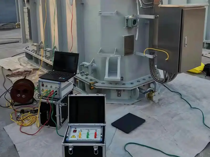
- Signal Injection: An SFRA instrument injects a low-voltage sinusoidal AC signal (typically 10V to 20V peak-to-peak) across a wide frequency band (20 Hz to 2 MHz) into one end of a transformer winding.
- Response Measurement: The instrument precisely measures the magnitude and phase of the output signal at the other end of the winding.
- Transfer Function Calculation: The instrument automatically calculates the ratio of the output signal to the input signal at various discrete frequency points, generating the frequency response curve.
- Baseline Comparison: The currently measured curve is overlaid and compared with the transformer’s “baseline fingerprint.” The most ideal baseline data comes from the Factory Acceptance Test (FAT), commissioning tests, or data from a “sister transformer” of the same model from the same manufacturer.
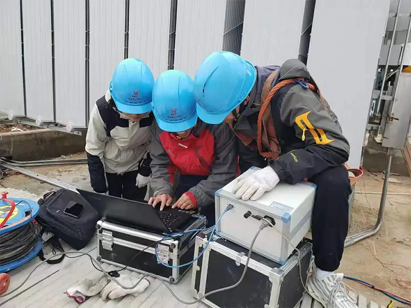
- Diagnostic Interpretation: Field engineers analyze the deviation and resonant point shifts between the current curve and the baseline to determine the severity of the mechanical fault.
Field Test Connections (for Targeted Diagnostics)
Open-Circuit Test: A signal is applied to one winding while all other windings of the transformer are left open and unterminated. This configuration is extremely sensitive to changes in the core’s magnetic properties and the overall macroscopic displacement of the windings.
Short-Circuit Test: While sweeping the primary winding, the corresponding secondary winding is short-circuited. This practice effectively removes the influence of the core’s magnetic circuit, allowing the tester to focus entirely on the leakage inductance and the physical geometry of the active winding.
What Faults Can a Frequency Sweep Test Detect?
- Winding deformation (axial/radial distortion, buckling, or local collapse) caused by strong short-circuit fault currents.
- Core displacement that occurs during long-distance transportation, earthquakes, or long-term operation.
- Loosening of clamping structures and loss of pressure in winding support structures.
- Internal electrical connection faults, including broken/loose leads or severe wear on tap changer contacts.
- Shorted core laminations and abnormal remanent magnetism issues.
How to Professionally Interpret SFRA Data: A Frequency Band Analysis
To accurately locate the specific physical location of a fault, engineers must analyze the Bode plot by dividing it into different frequency bands. Although the specific band divisions may vary slightly depending on the transformer’s capacity, the generally accepted diagnostic matrix is as follows:
| Frequency Band | Corresponding Core Component | Key Diagnostic Focus & Fault Interpretation |
|---|---|---|
| Low-Frequency (< 2 kHz) | Main Magnetic Circuit (Core) | Curve deviations indicate mechanical core displacement, internal lamination shorts, significant remanent magnetism, or poor core grounding. |
| Mid-Frequency (2 kHz - 20 kHz) | Overall Winding Structure | Shifts in resonant points suggest a loss of clamping pressure, overall winding movement or displacement, or severe coil misalignment. |
| High-Frequency (20 kHz - 400 kHz) | Inter-turn Micro-Geometry | This is the most critical region for detecting local winding deformation, buckling, abnormal inter-turn capacitance changes, or local coil collapse. |
| Very High-Frequency (> 400 kHz) | Internal Leads & Test Grounding | Data anomalies typically reflect zero-sequence issues, poor tap changer contact, broken internal leads, or interference from field grounding. |
A Practical Tip for Field Engineers: How to Avoid Misdiagnosis
Many inexperienced testers often misinterpret severe waveform distortions in the >400 kHz very-high-frequency band as a catastrophic internal fault in the transformer. However, in real-world field situations, 80% of high-frequency anomalies are actually caused by poor test grounding, not a problem with the transformer itself.
The secret to eliminating “false positive” misdiagnoses is to use a short, flat braided copper grounding strap, clamped directly and firmly to the main transformer tank for grounding. Keep the unsupported length of test cables as short as possible, avoid sharp bends in the cables to reduce parasitic inductance, and repeatedly check the shield’s grounding status before making a final diagnosis.
When Should a Frequency Sweep Test Be Performed?
SFRA is not a routine maintenance test that needs to be performed monthly, as it requires the transformer to be de-energized and taken offline for connection. It is primarily performed at the following key high-risk trigger points:
- Factory Acceptance Test (FAT): To establish the most reliable “birth certificate” fingerprint for the transformer, serving as a baseline for its entire lifecycle.
- After Long-Distance Transport and Installation: To verify that the internal mechanical structure has not shifted during shipping by sea, rail, or road.
- Post-Severe Short-Circuit Fault Investigation: To assess whether the windings have physically deformed under immense electromagnetic forces immediately after a severe external short-circuit or lightning strike.
- After Strong Vibration Events like Earthquakes: To confirm that the core and coils are still securely fastened and undamaged.
- Pre-Commissioning and Pre-Major Overhaul Assessment: As a final mechanical check before a new transformer is connected to the grid, or to provide critical internal condition evidence before deciding to refurbish or retire an aging asset.
Frequently Asked Questions about SFRA Testing
1. Is the SFRA test destructive or will it damage the transformer’s insulation?
Absolutely not. SFRA is a 100% non-destructive, offline test. It uses a very low-voltage (often only 10V to 20V peak-to-peak) high-frequency AC signal that has no negative impact on the transformer’s insulation materials or operational lifespan.
2. Can an SFRA test still be performed if there is no historical baseline curve for the same transformer?
While having the original trace for the unit is ideal, you can still obtain extremely valuable diagnostic information in the absence of a baseline. Engineers typically use a “comparative method”—superimposing and comparing the response curves of different phases within the same transformer (e.g., Phase A vs. Phase B) or using the curve from a “sister transformer” of the same design and batch as a temporary reference.
3. How long does it take to perform a complete SFRA test?
The actual time for the instrument to perform a single-phase sweep measurement is very short, usually just a few minutes. However, the pre-test setup—including applying for a lockout-tagout (LOTO) permit, disconnecting high and low voltage busbars, and performing meticulous test lead arrangement and grounding—can take several hours, depending on the complexity of the substation site.
EXPERT GUIDANCE
Need Help Choosing the Right Testing Equipment?
Summary
Sweep Frequency Response Analysis (SFRA) is a non-destructive, cutting-edge diagnostic solution specifically designed to uncover hidden internal mechanical faults in transformers (such as severe winding deformation and core displacement) that conventional tests easily miss. Its core principle is to analyze the transformer’s unique RLC network “electrical fingerprint” by plotting a Bode plot and comparing the current curve with a historical baseline, making even subtle structural changes visible.
SFRA is an indispensable safety verification step after transformer transportation, following a short-circuit impact, and before making major overhaul decisions, aimed at preventing catastrophic outages caused by latent internal damage. Achieving high diagnostic accuracy is highly dependent on top-tier test instruments and stringent field grounding practices, as poor-quality equipment can easily introduce interference noise, leading to serious misdiagnosis.
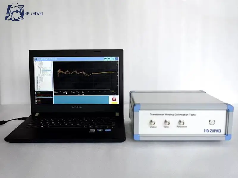
Ensure Transformer Integrity with ZHIWEI SFRA Testing Solutions
Accurate SFRA testing depends entirely on the reliability of your equipment. Inconsistent test leads, poor signal-to-noise ratio (SNR), or non-compliant hardware can lead to false diagnostics—resulting in unnecessary, costly tank teardowns or, worse, missed faults that cause catastrophic grid failure.
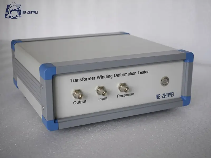
At ZHIWEI, we engineer our Sweep Frequency Response Analyzers to meet the rigorous demands of real-world substations and global compliance standards (IEEE C57.149, IEC 60076-18). Our solutions are designed to solve the biggest pain points for substation engineers and procurement teams:
✅ Superior Safety & Interference Rejection: Ensure operator safety with 5000V isolation. Advanced hardware and software noise suppression deliver smooth, accurate, and repeatable SFRA curves, even in the most challenging substation environments.
✅ Ultra-Fast Scanning: Minimize transformer downtime with high-speed measurements in just 1-2 minutes per phase. A wide 10Hz-2MHz frequency range and customizable settings maximize your team’s on-site efficiency.
✅ Smart, Compliant Diagnostics: Fully compliant with IEC 60076-18. Easily overlay up to 9 curves, get automatic correlation analysis, and export professional Word/JPG reports with one click for intuitive, actionable insights.
✅ Lifetime Expert Support: Your purchase is backed by a professional team, a 1-year warranty, and lifetime technical guidance. Count on our experts to help you interpret complex results and ensure your diagnostic confidence every time.
Contact ZHIWEI today to upgrade your diagnostic toolkit with industry-leading SFRA testing equipment and safeguard your electrical infrastructure!


