
No-load and load operations are common states for transformers. A solid understanding of both no-load and load principles, combined with accurate testing, is vital for design optimization, fault diagnosis, and energy‑efficient operation.
However, a complete picture of transformer health, crucial from its manufacturing floor to its operational lifespan, involves more than just these parameters. Other fundamental diagnostic tests, such as transformer ratio testing and transformer DC resistance testing, are equally vital for assessing winding integrity, connection quality, and overall operational readiness, and no further elaboration is provided here.
This article uses the ZWKZ204 no-load and load loss tester to walk through test procedures, key data handling, and common issues with remedies—providing a practical technical reference for power industry professionals.
Basic Concepts and Principles of Transformer No-Load and Load Operation
Definition and Characteristics of No-Load Operation
No-load operation means the primary winding is connected to an AC source at rated frequency and voltage, while the secondary winding is open (no load).
Under this condition, the transformer only draws a small magnetizing (no-load) current from the grid to sustain the alternating flux in the core. Energy loss is mainly no-load loss (core loss), which includes hysteresis and eddy-current losses.
Key features during no-load operation:
Secondary voltage is approximately rated voltage (neglecting leakage reactance drops).
Primary (no-load) current is very small—typically 2%–8% of rated current.
The magnetizing current exists because the core must be energized. Its waveform is not a pure sine and contains significant harmonics, which is one of the main causes of transformer noise.
Definition and Characteristics of Load Operation
Load operation means the primary is supplied at rated conditions and the secondary supplies a load. The secondary current produces magnetomotive force (MMF) that partially demagnetizes the primary MMF.
To keep the core flux nearly constant, the primary current increases to oppose the secondary MMF.
Losses under load include:
No-load (core) loss, independent of load current.
Load (copper) loss, proportional to the square of load current, caused by winding resistance.
Leakage reactance causes voltage drop under load; thus secondary voltage slightly falls as load increases (especially with inductive loads).
Purposes and Procedures of No-Load and Short-Circuit Tests
Objectives of the No-Load and Load Test
- Measure no-load loss and no-load current: verify compliance with design specs; detect issues in core material, lamination quality, or core joints. Excessive no-load current may indicate insufficient turns or abnormal core magnetic path.
- Check winding group connections and polarity: confirm connection groups (e.g., Y/Y, Δ/Y) and prevent misconnection-related faults.
- Measure load losses and short-circuit voltage (see short-circuit test section): load loss reveals winding resistance and possible inter-turn shorts.
No-Load Test Procedure
No-load tests are usually done by applying voltage to the low-voltage side while the high-voltage side is open. Steps:
Preparation:
- Isolate the transformer from the grid, remove external leads, clean surfaces and terminals.
- Check test equipment (variac, voltmeter, ammeter, wattmeter) for accuracy and integrity. Ensure reliable grounding.
Wiring:
- Connect the variac output to the transformer’s low-voltage winding; keep the high-voltage winding open.
- Place an ammeter in series on the low-voltage side for no-load current measurement and a voltmeter in parallel for voltage.
- Connect the wattmeter with its voltage coil in parallel and current coil in series on the low-voltage side; observe wattmeter polarity to avoid reversed readings.
measurement:
- Slowly raise the variac until the low-voltage side reaches rated voltage (Un). Record the no-load current (I0) and no-load loss (P0).
- For comprehensive core analysis, measure I0 and P0 at multiple voltages (e.g., 0.8Un, 0.9Un, 1.0Un, 1.1Un, 1.2Un) and plot I0–U and P0–U curves.
Post-test handling:
- Reduce variac to zero, cut power, allow windings to discharge, then remove test connections.
- Organize test data and compare with design or standard values to judge no-load performance.
Load (Short-Circuit) Test Procedure
Load (short-circuit) tests are normally done by applying voltage to the high-voltage side while shorting the low-voltage side. Steps:
Preparation:
Similar to no-load prep. Because currents are large, choose a variac and short-circuit conductors with adequate capacity and low resistance to prevent heating-related errors.
Wiring:
- Connect variac output to the high-voltage winding; short the low-voltage winding with heavy shorting leads.
- Place an ammeter in series on the high-voltage side to measure short-circuit current, and a voltmeter in parallel to measure applied voltage.
- Connect wattmeter voltage coil in parallel and the current coil in series on the high-voltage side.
measurement:
- Slowly increase applied voltage so the short-circuit current rises toward rated current (In). Record the short-circuit voltage (Uk) and load loss (Pk) at In.
- For characteristic curves, measure at currents such as 0.5In, 0.75In, 1.0In and plot Pk–I and Uk–I.
- Note: load loss increases with winding temperature; correct measured values to a reference winding temperature (commonly 75°C for copper or 115°C for aluminum).
Post-test handling:
- Cut power, remove shorting leads and test wiring, inspect windings for overheating or deformation.
- Calculate percent short-circuit voltage: Uk% = Uk / Un × 100%. Compare against standard or design values.
Test Data Processing and Analysis
No-Load Test Data Processing
No-load loss correction: No-load loss is mainly core loss and is not a strong function of winding temperature, but test conditions may differ from the standard reference temperature (usually 20°C).
Correct the measured power using the wattmeter temperature correction factors:
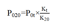
Note: P020 is no-load loss at 20°C, P0t is measured loss at test temperature t, and K20 and Kt are the wattmeter temperature factors at 20°C and t°C respectively.
No-load current analysis: The rated percentage of no-load current (I0% = I0 / In × 100%) should meet the design requirements.
Typical ranges:
Small/medium transformers: I0% ≈ 3%–8%
Large transformers: I0% ≈ 1%–3%
Excessive I0% may indicate wide gaps between laminations, core grounding (multiple contact points), or insufficient turns. Very low I0% could imply too many turns, though that’s rare.
Load Test Data Processing
Load loss correction:Load loss depends on winding resistance, which varies with temperature. Correct measured load loss to a reference winding temperature (copper: 75°C; aluminum: 115°C) using:
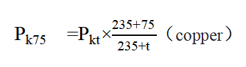
Note: Pk75 is the load loss at 75°C, Pkt is the measured load loss at test temperature t, and 235 is the reference base for copper’s temperature coefficient.
Short-circuit voltage analysis: Uk% is an important parameter, typically 4%–10.5% depending on capacity and voltage class.
High Uk% increases voltage regulation sensitivity under load; low Uk% yields higher short-circuit currents and may hamper protection coordination.
Big deviations from design Uk% may imply incorrect turn counts or conductor cross-section errors.
Common Problems in No-Load and Load Operation and Remedies
No-Load Issues
Excessive no-load loss
Causes: Deteriorated lamination insulation increasing eddy losses; loose core laminations increasing magnetic reluctance and hysteresis losses; inter-turn shorts causing extra circulating losses.
Remedies: Replace deteriorated lamination insulation; re-clamp core laminations to reduce joint gaps; inspect winding insulation and repair inter-turn shorts (if severe, rewinding may be required).
Abnormally high no-load current
Causes: Multiple core grounding points causing circulating currents; insufficient turns reducing MMF; poor core material with low permeability.
Remedies: Locate and remove grounding points or repair insulation; verify winding turns and rewind if necessary; replace substandard core material during manufacturing (in-service replacement is rarely feasible—use compensation measures instead).
Load Operation Issues
Excessive load loss
Causes: Undersized conductor cross-section raising current density and resistance losses; inter-turn or inter-layer shorts from winding faults; prolonged overload operation.
Remedies: Replace conductors with correct cross-section; repair winding insulation; avoid overload—keep load factor ideally below ~80%; replace transformer if capacity is insufficient.
Excessive secondary voltage drop
Causes: Highly inductive load with low power factor increasing leakage voltage drop; excessive leakage reactance from winding design or poor conductor arrangement; long-term overload raising winding resistance.
Remedies: Install power-factor correction capacitors on the load side; optimize winding design to reduce leakage reactance; properly manage loads or upgrade transformer capacity.

Conclusion
No-load and load testing are key parts of a transformer’s lifecycle. They are essential for evaluating transformer performance and detecting latent faults.
By understanding no-load and load principles, following standardized test procedures, accurately processing data, and promptly addressing common problems, you can improve transformer reliability and energy efficiency—helping secure stable power system operation.
Using integrated testers like the ZWKZ204 enables efficient on-site measurement, curve recording, harmonic analysis, and data export, thereby raising test quality and project delivery efficiency.
Consult Us | Schedule Demo | Get a Quote
Appendix: ZWKZ204 Key Specifications & Highlights
Measurement Functions: No-load loss/current, load loss, impedance voltage; voltage, current, power, phase angle; phasor diagrams.
Harmonics & Waveforms: 1st–32nd harmonic analysis; real-time viewing and zooming of voltage/current waveforms.
Curve Recording: Automatic recording of no-load characteristic curves to aid core performance analysis.
Display & Operation: 7-inch true-color touchscreen with emWin interface for full touch control.
Data Management: Built-in database; supports DBF format USB export (directly viewable/editable/printable/archivable with Excel); supports record query and on-site printing.
Ranges & Accuracy:
Voltage: Phase voltage 0–500V (Line voltage up to 800V)
Current: 0.1–100A (Supports external CT for extended range)
Accuracy: 0.2% (for power factor 1.0–0.2), 1% (for power factor 0.2–0.01)
Other: ARM processor, 128MB RAM (expandable to 4GB); AC 220V±15% power supply; -10°C to 40°C operating temperature; approx. 3.5 kg weight; non-volatile clock.
Usage Tips: Ensure reliable grounding. Before testing, correctly set CT/PT ratios, test methods, correction temperatures, and material types. Follow the wiring manual, slowly ramp up the voltage/current, and after testing, return to zero before powering off and disconnecting.


