
Current Transformers (CT) and Potential Transformers (PT), collectively known as instrument transformers, are indispensable core sensing components in high-voltage grids. They accurately and reliably convert dangerous primary high currents and voltages into standard low-level signals for secondary protection and metering devices.
If the performance or accuracy of a CT or PT degrades, the consequences range from massive revenue metering losses to catastrophic events like protection relay misoperations (failure to trip or unneeded tripping), substation fires, and widespread blackouts. Therefore, comprehensive performance testing of CTs and PTs is a mandatory requirement in power regulations, whether during pre-commissioning handover tests or routine maintenance tests during operation.
This guide will detail the key indicators that must be evaluated during CT/PT testing, helping electrical engineers ensure long-term grid reliability and compliance with international standards such as IEC 61869 (which replaced the IEC 60044 series) and IEEE C57.13.
The Role of CT and PT in Power Systems
Before diving into specific testing indicators, we must clarify the fundamental functional differences between these two types of equipment:
Current Transformer (CT): Its core task is to output a secondary current (typically 1A or 5A) strictly proportional to the primary current. Its performance focuses on avoiding premature saturation under heavy fault current impacts and maintaining sufficient accuracy to ensure the protection system can accurately identify and clear faults.
Potential Transformer (PT/VT): Its core task is to output a secondary voltage (typically 100V or 110V) strictly proportional to the primary voltage. Its performance focuses on stability and dielectric (insulation) reliability under long-term high voltage stress, ensuring accurate metering and voltage protection.
Core Testing Indicators for Current Transformers (CT)
To fully validate the performance of a current transformer, field engineers must measure the following key indicators:
1.Ratio and Angle Error
The ratio test aims to verify whether the CT steps down current strictly according to its nameplate rating (e.g., 1000/5A). The angle error measures the phase shift between the primary and secondary currents. In revenue metering or gateway metering, even a 0.1% ratio error or a slight phase displacement can accumulate into staggering billing discrepancies and financial losses over the years.
2.Excitation / Saturation Curve
Excitation characteristic testing is the most critical item for protection-class CTs. This test plots the voltage-current curve to precisely pinpoint the CT’s “knee point voltage”—the critical point where a 10% increase in secondary voltage results in a 50% increase in exciting current. If a CT’s knee point voltage is too low, it will saturate prematurely during a grid short-circuit fault, failing to transfer the true fault current to the protection relay. This can eventually lead to breaker failure to trip and catastrophic fault escalation.
3.Winding Resistance
Measuring the DC resistance of the secondary winding is primarily used to calculate the total burden of the CT and assess its internal health. If the winding resistance is significantly higher than the factory value, it usually indicates internal wire aging, poor terminal connections, or manufacturing defects. This not only affects the CT’s accuracy class but may also lead to overheating damage during continuous operation.
4.Polarity Check
Polarity defines the instantaneous direction of the secondary current relative to the primary current. Incorrect polarity will directly cause directional protection relays (such as differential protection) to fail to operate during internal faults and to trip mistakenly during external faults, severely disrupting the grid’s protection logic with disastrous consequences.
Core Testing Indicators for Potential Transformers (PT)
PT testing shares similarities with CT testing, but its indicators focus more on voltage stability and dielectric strength.
1.Voltage Ratio and Phase Displacement
Similar to CTs, the PT ratio test verifies if its primary-to-secondary voltage transformation conforms to the nameplate value (e.g., 110kV/110V). The phase displacement must be sufficiently small to ensure the accuracy of power factor calculations, energy metering, and directional protection.
2.Burden Measurement
Burden refers to the total impedance (in VA) of all meters, relays, and control devices connected to the PT’s secondary side. This test ensures that the actual operating burden does not exceed the PT’s rated capacity. Overloading causes a significant drop in secondary voltage, potentially triggering false judgments and misoperations of undervoltage relays.
3.Insulation Resistance
Because PTs are continuously connected across high-voltage lines, their insulation systems endure constant electrical stress. Using a megohmmeter for insulation resistance (IR) testing is a crucial preventive measure to assess the insulation status, detect moisture ingress or aging defects early, and avoid high-voltage short-circuit accidents caused by dielectric breakdown.
Comparison: Key Testing Parameters for CT vs. PT
For quick reference, the table below summarizes the key testing differences between CTs and PTs:
| Testing Indicator | Current Transformer (CT) | Potential Transformer (PT) | Primary Purpose |
|---|---|---|---|
| Ratio Test | Primary/Secondary Current Ratio | Primary/Secondary Voltage Ratio | Verify nameplate accuracy for precise transformation |
| Phase Error | Current Phase Displacement | Voltage Phase Displacement | Ensure accurate metering and directional protection |
| Excitation Test | Mandatory (Measure knee point) | Not Applicable | Prevent CT saturation during faults to ensure protection operation |
| Winding Resistance | Secondary DC Resistance | Primary & Secondary DC Resistance | Calculate burden and identify internal connection defects |
| Insulation | Important | Crucial | Prevent dielectric breakdown and high-voltage short circuits |
| Polarity | Mandatory | Mandatory | Ensure directional protection logic operates correctly |
Upgrade Your Substation Testing with the ZWH101 CT/PT Analyzer
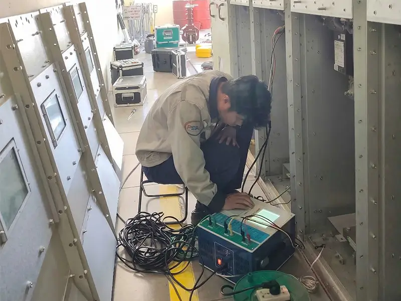
Traditional instrument transformer testing often involves carrying multiple heavy standalone devices (e.g., boosters, ratio bridges, resistance testers), complex on-site wiring, long testing cycles, and manual data recording. Moreover, testing high-knee-point CTs poses extreme safety risks. These pain points severely restrict the efficiency and safety of field testing.
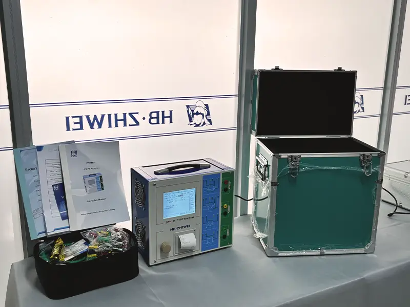
The ZWH101 CT/PT Analyzer is the next-generation solution designed specifically to overcome these challenges.
It integrates all essential testing functions into a single portable device weighing less than 9 kg, providing an efficient, one-stop testing experience for power industry users:
Solving the Pain Points: From Slow & Complex to Fast & Simple
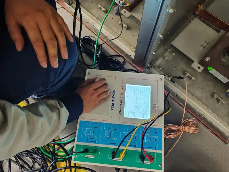
One-Click Automated Testing: With just a single wiring connection, the ZWH101 automatically completes all key tests, including CT excitation, ratio, polarity, winding resistance, and phase error, condensing hours of work into just minutes.
Solving the Pain Points: From Hazardous to Safe
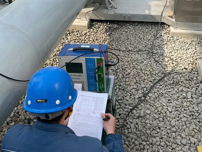
Innovative Low-Frequency Principle: Without applying dangerous high voltages, the instrument can accurately measure protection-class CTs with equivalent knee point voltages up to 45kV using a maximum safe voltage of 180V, fundamentally eliminating on-site safety hazards.
Solving the Pain Points: From Disorganized to Managed
Intelligent Data Management & Reporting: The device can store up to 2,000 sets of test data, which can be easily exported to a PC via a USB drive. Its companion software automatically generates standard-compliant MS Word test reports, complete with full curves and data, drastically improving data management and reporting efficiency.
Comprehensive Compliance
The ZWH101 fully complies with international standards such as IEC 61869, IEC 60044, and IEEE C57.13. Its automatically calculated key parameters, including Knee Point, ALF, FS, and Ts, are highly accurate and reliable, ensuring your test results carry authority in any scenario.
Whether for grid companies, power plants, testing service providers, or large industrial and mining enterprises managing their own substations, the ZWH101 CT/PT Analyzer is the ultimate tool for verifying instrument transformer performance, boosting operational efficiency, and safeguarding grid security.
Ready to say goodbye to cumbersome and inefficient traditional testing?
Contact us today to request detailed technical specifications and a quotation for the ZWH101 CT/PT Analyzer!


