
While they are both resistance testers, Insulation Resistance Testers and Earth (Ground) Resistance Testers serve completely opposite purposes. The former prevents current leakage, while the latter guides current safely into the ground.
During electrical installation acceptance, equipment maintenance, or troubleshooting, many people confuse the two due to their similar names. This can lead to purchasing the wrong expensive equipment, non-compliant test reports, or even leaving behind safety hazards.
This article uses a 1-minute comparison table and scenario-based analysis to help you clearly distinguish between them and make precise selection decisions.
Understand the Core Differences in 1 Minute
| Comparison Dimension | Insulation Resistance Tester | Earth Resistance Tester |
|---|---|---|
| Object of Measurement | The current leakage path in insulating materials (e.g., between conductor and casing, or between wires) | Continuity resistance between the grounding electrode and the earth (dissipation path for fault currents) |
| Output Method | High Voltage DC (500V–10kV, adjusted by scenario) | AC / Low Frequency Current (to avoid stray current interference) |
| Typical Range | ≥0.5MΩ (Pass value), commonly 1MΩ–10GΩ | Generally < 10Ω (standard), critical systems < 1Ω |
| Connection Method | Line (L) + Earth (E) + Guard (G, optional for shielding) | 3-Pole (Current + Pot. + Earth), 4-Pole (eliminates lead resistance), Clamp Method |
| Common Standards | IEC 60364-6, IEC 61557-2 | IEC 60364-6, IEC 61557-5, IEEE 81 |
| Functional Limits | Cannot measure earth resistance (High voltage DC disrupts the ground environment; results are invalid) | Cannot test insulation performance (Voltage is too low to detect high-voltage leakage) |
Quick Selection Conclusion:
Insulation Resistance Tester: Use this when you need to confirm “Is the insulation layer intact? Is there any current leakage?” (e.g., acceptance after laying new cables, maintenance of damp motors).
Earth Resistance Tester: Use this when you need to confirm “Is the grounding system clear? Can it quickly drain fault currents?” (e.g., lightning protection engineering acceptance, substation ground grid testing).
Now that you understand the core differences, we will dive deeper into each instrument below to help you better understand their working principles and applications.
Insulation Resistance Tester: Preventing Current Leakage
What is an Insulation Resistance Tester?
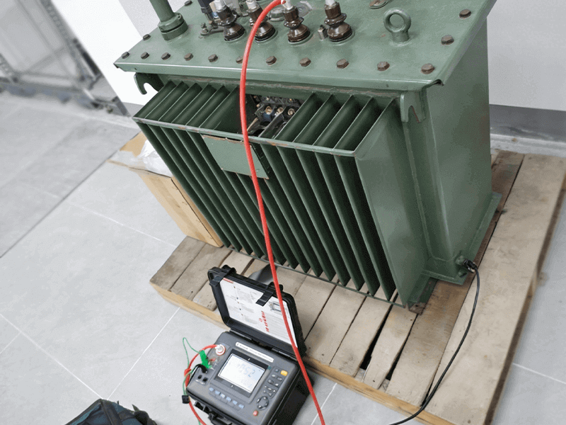
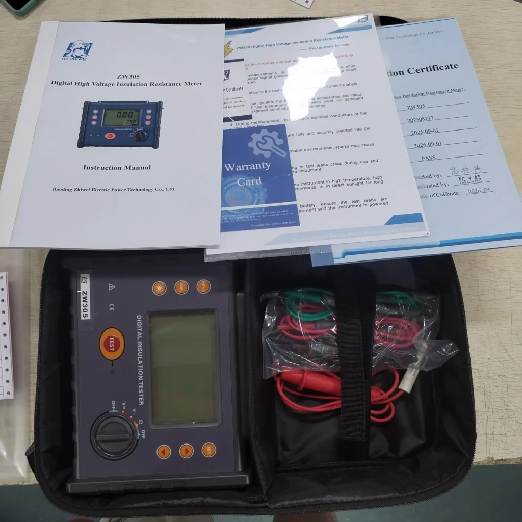
Insulation Resistance Tester, also known as a Megohmmeter (or Megger), its core function is to measure the ability of insulating material to resist current leakage by applying high DC voltage. The higher the insulation resistance value, the better the insulation performance, effectively preventing equipment damage or electric shocks caused by leakage.
Core Features and Working Principle
Working Principle: Applies high DC voltage (e.g., 500V, 1000V, 2500V) to the insulation material, measures the stable value of capacitive current, absorption current, and conduction current, and calculates the insulation resistance using Ohm’s Law R=V/I.
Key Indicators: Absorption Ratio (DAR) and Polarization Index (PI). generally, a DAR ≥ 1.3 indicates good insulation, while a value close to 1 suggests dampness.
Testing Requirements: Should be performed in an environment of 10°C–25°C and 40%–70% relative humidity. The power supply to the equipment under test must be disconnected to avoid damaging electronic components.
Typical Application Scenarios
Industrial Equipment: Detecting insulation aging in motor windings and transformer coils.
Cable Testing: Checking for cracks or degradation in the insulation layer after high-voltage cables are laid.
Home Appliances: Pre-delivery safety testing to ensure insulation between live parts and the casing, preventing electric shock.
Earth Resistance Tester: Guiding Current Safely to Ground
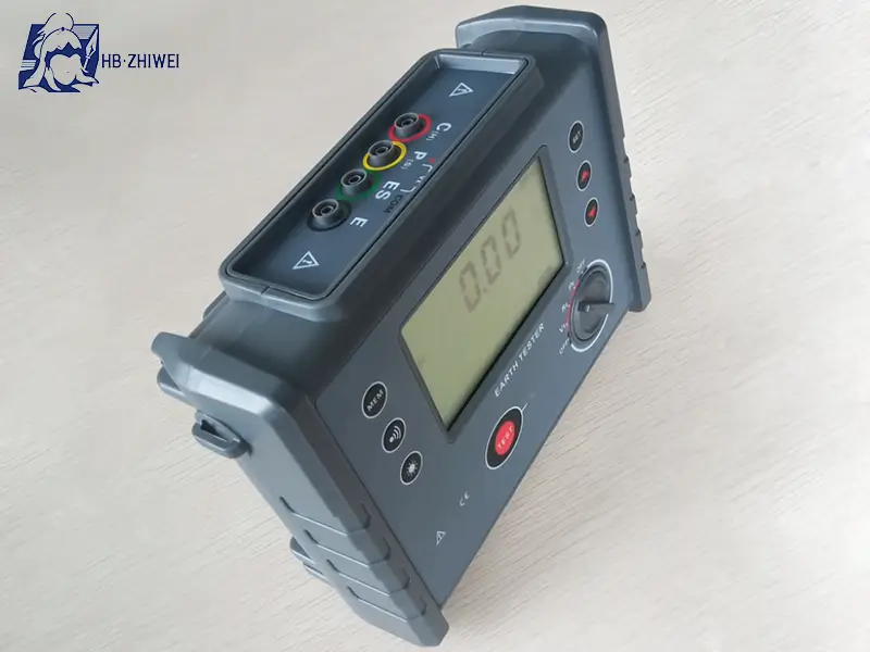
What is an Earth Resistance Tester?
Earth Resistance Tester (also known as a Ground Tester), measures the continuity resistance between the grounding electrode and the earth. The core purpose is to ensure that fault currents and lightning currents can quickly dissipate into the earth through the grounding system, protecting equipment and personnel. The lower the earth resistance value, the better the dissipation effect.
Core Features and Test Methods
Working Principle: Injects AC or low-frequency test current, measures the voltage drop between the grounding electrode and the auxiliary electrode, then calculates the earth resistance.
Mainstream Test Methods:
(1) 3-Pole Method (Fall-of-Potential): The current electrode, voltage electrode, and the grounding electrode under test are arranged in a straight line. Suitable for open areas (e.g., substations).
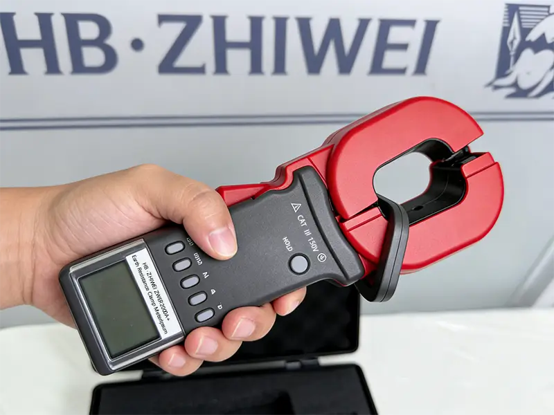
(2) Clamp Method: No auxiliary stakes are required; it clamps directly onto the ground wire. Suitable for dense urban areas or scenarios where auxiliary electrodes cannot be placed.
(3) 4-Pole Method: Eliminates interference from test lead resistance, offering higher measurement precision.
Influencing Factors: Soil resistivity, humidity, and temperature (rain or frozen soil can cause measurement errors).
Typical Application Scenarios
Lightning Protection Systems: Acceptance testing of lightning rods and lightning protection grounding grids.
Power Systems: Routine maintenance of grounding grids in substations and power plants.
Construction & PV: Grounding acceptance for residential buildings and solar panel grounding detection (to avoid shock and efficiency loss).
Critical Misconceptions: Never Substitute One for the Other!
Using The Insulation Tester for Earth Resistance = Invalid Test
The high-voltage DC from a Megohmmeter can polarize moisture in the soil or break down anti-corrosion layers, resulting in measurements far exceeding actual values. It cannot reflect the true grounding dissipation capability.
Using The Earth Tester for Insulation = Waste of Time
Earth testers output low voltage with a small range. Even if a value is measured, it cannot determine whether the insulation can withstand leakage current under actual operating voltage.
If Ignoring Site Conditions When Choosing Methods
Forcing the use of the 3-Pole method (requiring stakes) in dense urban areas will lead to failure (e.g., concrete ground). In this case, you should choose a Clamp Earth Tester. When testing insulation in the field, equipment must be dried first if the environment is highly humid.
Selection Guide: Precise Matching by Scenario
Quick Selection by Scenario
| Scenario | Recommended Instrument | Key Parameter Requirements |
|---|---|---|
| Motor, Cable, Transformer Maintenance | Insulation Resistance Tester | Test voltage 500V/1000V/2500V, supports PI/DAR, Range ≥10GΩ. |
| Lightning Protection, Substation Ground Grid | Earth Resistance Tester | Supports 3-Pole/4-Pole methods, Range 0.01Ω–2000Ω, high anti-interference capability. |
| Residential / Office Building Grounding | Earth Resistance Tester (Clamp) | No stakes needed, Range 0.1Ω–1200Ω, portable and easy to operate. |
| Home Appliance Factory Testing | Insulation Resistance Tester | Test voltage 200V–500V, Range ≥4MΩ, supports timed testing (1 min). |
In actual projects, you usually need both, depending on the testing requirements. Insulation testing protects the internal integrity of the equipment, while grounding testing protects the safety of the external discharge path.
FAQ: Insulation Resistance Tester vs. Earth Resistance Tester
Q1: Can I use an insulation resistance tester to measure earth resistance?
Absolutely not. Using the wrong tool will result in inaccurate readings and potential safety hazards. Insulation Resistance Tester measure whether equipment/cables leaks current. The two differ completely in measurement objects, test methods, and magnitude (MΩ/GΩ vs. Ω).
Q2: Can I use a standard multimeter to measure insulation resistance?
Generally, no. A standard digital multimeter uses low voltage (typically 3V-9V) to measure resistance, which is not enough to stress the insulation material. An Insulation Resistance Tester (Megohmmeter) generates high DC voltage (250V up to 10kV) to detect moisture or aging issues that a multimeter would miss.
Q3: When can’t I use a Clamp Earth Tester?
When the grounding system is a single-point ground with no closed loop (e.g., a single down-conductor for home lightning protection), the clamp method cannot form a current loop. You must switch to the 3-Pole method.
Q4: What safety precautions must be taken for insulation testing?
You must follow the three steps: Disconnect, Verify (dead circuit), and Discharge. For circuits containing sensitive electronic components (e.g., VFDs, SPD, PLC modules), isolate them according to the manufacturer’s guidelines to avoid damage from high voltage.
Q5: If I encounter “Breaker Tripping / Live Casing”, should I test insulation or grounding first?
Generally, after safety isolation, prioritize Insulation Resistance Testing to locate leakage paths. If insulation is normal, then suspect grounding failure and perform Earth Resistance and Continuity checks. Both tests are often required for troubleshooting.
Conclusion
Insulation Resistance Testers and Earth Resistance Testers stand as the two pillars of electrical safety assurance, safeguarding the safe, stable, and efficient operation of power supply systems. They cannot replace each other. Just remember: Insulation Testers check insulation to prevent leakage, while Earth Testers focus on ensuring the safety of the external discharge path.
Ensuring Electrical Safety Starts with the Right Equipment
Whether you need a high-precision Insulation Resistance Tester for motor maintenance or an anti-interference Earth Resistance Tester for complex field installations, ZHIWEI provides cost-effective, professional solutions.
Contact us today for expert selection advice, or provide your equipment type and voltage level, and we will customize a testing compliance checklist for you.


