
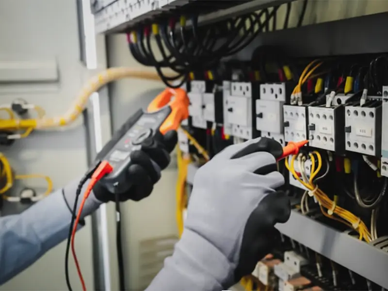
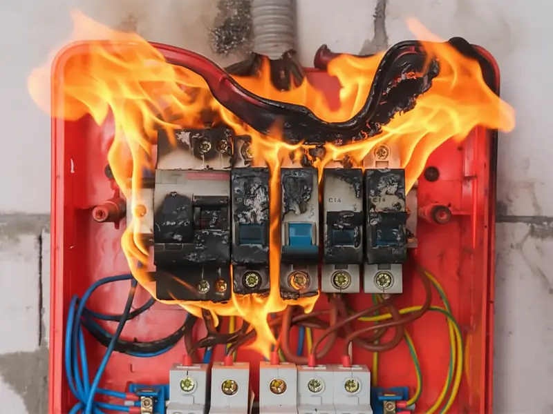
In industrial electrical systems, the integrity of insulation directly determines the operational lifespan of equipment and the safety of production. Insulation failure doesn’t just lead to downtime losses; it is a primary cause of fires and electrical shock accidents.
The insulation resistance tester (commonly known as a Megger) is no longer just a simple measuring tool—it has become an indispensable diagnostic instrument for Preventive Maintenance (PdM) of industrial assets.
This article delves into the core technologies, selection criteria, and operational standards of insulation testing, helping O&M personnel achieve efficient asset verification and management.
Understanding Insulation Resistance Testing: Basic Principles and Formulas
Insulation resistance testing is a form of non-destructive testing (NDT) used to assess electrical insulation performance. Its core principle is based on Ohm’s Law (R=V/I).
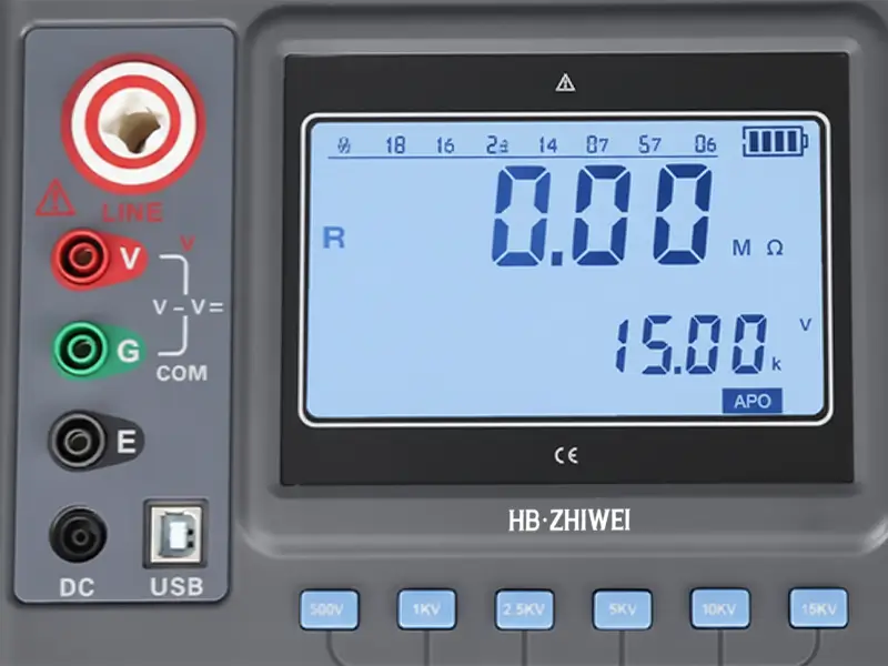
During the test, the instrument applies a specific high-voltage DC current (typically ranging from 500V to 10kV) to the target. By measuring the minute leakage current flowing through the insulation layer, it calculates the insulation resistance value (measured in MΩ or GΩ).
The resistance value directly reflects the insulation status: a higher value indicates intact insulation, while a low value suggests potential issues such as moisture ingress, contamination, or aging, requiring immediate troubleshooting to prevent short-circuit faults.
Two Core Testing Methods: From Basic Screening to Precision Diagnosis
In industrial scenarios, the choice of testing method directly impacts data reliability. Relying solely on basic tests is often insufficient for complex diagnostic needs; professional-grade testing requires incorporating time variables for precise assessment.
1. Spot Reading Test (Short-Time Test)
This is the most basic method, where the test voltage is applied for a fixed duration (usually 60 seconds) and the value is read. It is suitable for quickly screening whether equipment insulation meets the standard.
However, it has significant limitations: it is highly sensitive to temperature changes. The test value for the same equipment at 40°C will be far lower than at 20°C. To ensure historical data is comparable, readings must be corrected to a baseline temperature (20°C or 40°C).
2. Time-Resistance Method (PI & DAR Methods)
This method leverages the absorption current characteristics of insulation materials. By using the ratio of resistance values at different time intervals, it eliminates environmental interference, making it the standard method for industrial equipment diagnosis.
Dielectric Absorption Ratio (DAR): This is the ratio of the resistance value at 60 seconds to the value at 30 seconds (DAR=R60s/R30s). The acceptable range is typically 1.25–1.6.
Polarization Index (PI): This is the ratio of the resistance value at 10 minutes to the value at 1 minute (PI=R10min/R1min). This metric is minimally affected by temperature and is the preferred method for testing large motors and transformers.
| Insulation Condition | Polarization Index (PI) Value |
|---|---|
| Dangerous | < 1.0 |
| Questionable | 1.0 – 2.0 |
| Good | 2.0 – 4.0 |
| Excellent | > 4.0 |
Procurement and Selection Guide: Three Critical Parameters You Cannot Ignore
When purchasing insulation resistance testers for industrial use, one must look beyond basic specs and comprehensively evaluate safety ratings and functional suitability. This prevents test distortion or safety risks caused by improper selection.
Test Voltage Range Matching
The range must precisely match the rated voltage of the equipment under test:
Low-voltage equipment (<600V): Use 500V or 1000V ranges.
Medium to high-voltage equipment (motors, cables, etc.): Requires 2500V, 5000V, or 10000V ranges.
High-end devices often feature a ramp voltage function, which increases voltage gradually to pinpoint insulation weak points without causing irreversible damage.
The Necessity of the Guard Terminal (G Terminal)
This is a crucial yet often overlooked feature, indispensable in harsh environments with high dust or humidity.
When testing dirty or oily equipment, surface leakage current can lead to false “insulation failure” readings. Connecting the Guard terminal bypasses surface leakage, ensuring the tester measures only the volume resistance of the insulation layer, thus guaranteeing data accuracy.
Safety Ratings and Protection Features
Electrical testing carries the risk of arc flash, so it is crucial to strictly match the appropriate safety rating:
CAT III 600V/1000V is suitable for distribution system testing, and CAT IV 600V is suitable for outdoor lines and service entrance testing. Furthermore, an automatic discharge function is an essential safety feature; it releases the capacitive energy stored in the cable after testing, preventing residual charge from causing electric shock accidents.
Troubleshooting Common Testing Errors
Even with high-end equipment, improper operation can lead to distorted data. Focus on avoiding these three types of errors:
1) Lack of Temperature Correction: Insulation resistance drops by roughly half for every 10°C rise in temperature. Failure to correct for this makes seasonal data comparison impossible.
2) Test Lead Issues: Damaged or low-quality leads can introduce interference during high-resistance measurements, causing unstable readings.
3) Unreleased Residual Charge: Disconnecting leads before discharge is complete not only affects data but also poses a shock hazard.
FAQ of Insulation Resistance
1. What is the minimum acceptable standard for insulation resistance?
The general rule of thumb is “1 MΩ for every 1000 Volts of rated voltage, plus an extra 1 MΩ.” For example, a 460V motor should measure ≥ 1.46 MΩ. In practice, any value below 100MΩ warrants investigation.
2. Can a multimeter replace an insulation resistance tester?
No. A multimeter typically tests at only 9V, which cannot simulate the operating voltage stress of the equipment or detect latent insulation defects.
3. What is the recommended calibration cycle?
To meet ISO and IEC compliance requirements, it is recommended to have the device calibrated annually by a certified laboratory.
4. What is the difference between analog and digital testers?
Analog testers allow for intuitive observation of charging and leakage current trends, while digital models excel at precise recording, automatic PI/DAR calculation, and providing safety alerts.
Elevate Diagnostic Precision: Contact ZHIWEI for Expert Support
Precise insulation testing is a critical step in safeguarding the value of your electrical assets.
ZHIWEI specializes in delivering highly reliable electrical testing solutions. Whether you are seeking the ideal 5kV/10kV insulation resistance tester for your facility or project, or require technical guidance on model selection, please do not hesitate to contact our technical team. We are dedicated to equipping you with precise, safe, and professional-grade instrumentation.


