
Transformer Turns Ratio (TTR) testing is a mandatory core diagnostic procedure used to verify the structural integrity of transformer windings and the operational status of tap changers. While testing in a lab setting is relatively simple, conducting field tests in an active substation means engineers must deal with extreme weather, space constraints, complex electromagnetic interference, and tedious data recording.
This guide will walk you through the professional Standard Operating Procedure (SOP) required to safely and accurately complete TTR tests in the field. It will also show you how to use advanced smart instruments to boost your field efficiency by over 60%.
What is a TTR Test and Why is it the Core of Preventive Maintenance?
The core purpose of a TTR test is to measure the ratio of turns between the transformer’s primary winding (high voltage) and secondary winding (low voltage). By applying a known low-voltage AC signal to the high-voltage side and accurately measuring the induced voltage on the low-voltage side, field engineers can calculate the exact turns ratio.
During substation spring inspections, major overhauls, or troubleshooting, field TTR testing is crucial for accurately pinpointing the following hidden issues:
- Winding Faults: Inter-turn short circuits, broken strands, or open circuits.
- Assembly Defects: Incorrect lead wiring or reversed internal polarity.
- Mechanical Wear: Poor internal contacts or mechanical jamming in On-Load Tap Changers (OLTC) or De-Energized Tap Changers (DETC).
- Parameter Drift: Abnormal deviations between actual operating parameters and factory nameplate ratings.
Pre-Test Preparation: Equipment List and Safety Protocols
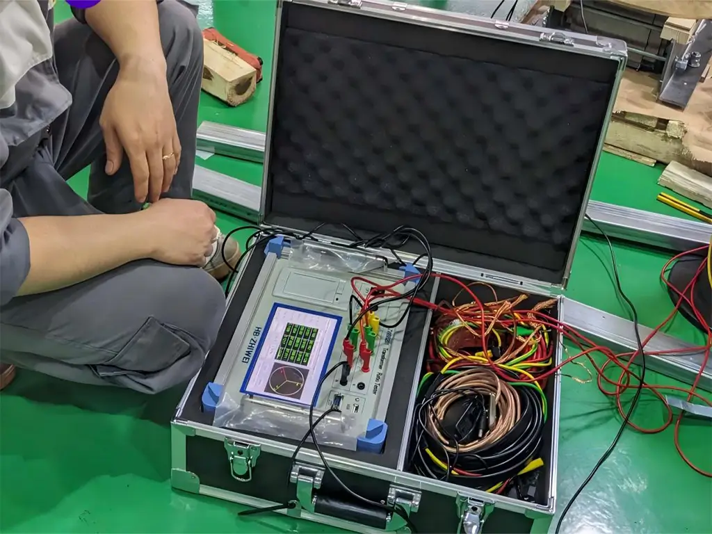
Core Test Equipment: ZHIWEI ZWBB201 Three-Phase Transformer Turns Ratio Tester.
Traditional single-phase instruments require users to climb the transformer to switch wiring frequently. In contrast, the ZWBB201 features an ARM processor and a new algorithm, allowing it to automatically complete a three-phase test in just 3 seconds with a single connection (no need to adjust three-phase power balance). Its built-in customizable lithium battery and 7-inch true-color touchscreen make it an excellent tool for handling complex field tasks.
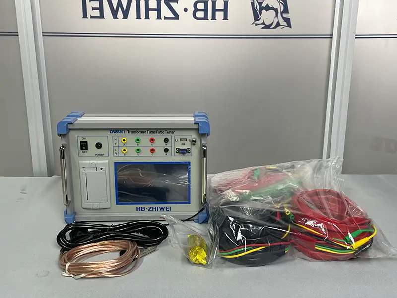
Test Accessories: Dedicated high-voltage (H) and low-voltage (X) test cables (using standard yellow, green, red, and black color coding), and heavy-duty test clips with strong bite force.
Personal Protective Equipment (PPE): Insulated hard hats, high-voltage insulated gloves, insulated boots, and safety goggles.
Auxiliary Tools: Lockout/Tagout (LOTO) kit, portable grounding cables, and wire brushes for cleaning heavily oxidized terminals.
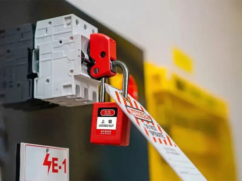
Safety First: The 3 Core Steps of LOTO
No matter the substation’s voltage level, Lockout/Tagout (LOTO) is an absolute life-saving rule. The following steps must be strictly followed before testing:
- Disconnect and Isolate: Disconnect all power sources on both the high and low-voltage sides of the transformer, including high-voltage circuit breakers and all low-voltage disconnect switches.
- Verify and Discharge: Use a voltage detector rated for the appropriate voltage to confirm there is zero voltage on all bushing terminals. Then, immediately use a grounding rod to fully discharge all terminals for at least 1 minute to eliminate any residual capacitance.
- Lock and Tag: Place “Do Not Operate – Personnel at Work” warning tags on all control panels and mechanisms that could cause switching. Apply physical locks, keeping the keys solely in the possession of the lead field worker.
EXPERT GUIDANCE
Need Help Choosing the Right Testing Equipment?
Field SOP: Master TTR Testing in 7 Steps
To ensure data accuracy and personnel safety, please strictly follow these steps:
Step 1: Inspect the site and confirm isolation
Upon arriving at the transformer, first do a visual patrol of the perimeter. Reconfirm that all switches are open, LOTO tags and locks are intact, and safety fences have been set up around the work area.
Step 2: Carefully check the transformer nameplate
Record key parameters from the nameplate: high/low-side rated voltages, vector group (e.g., Y/y, D/d, ZN/y), polarity, tapping range, and tap step size.
Step 3: Set the tap changer to the starting position
Set the OLTC or DETC to its rated tap (or the lowest tap). Ensure that the control power for operating the tap changer remains disconnected during the test (if operating manually).
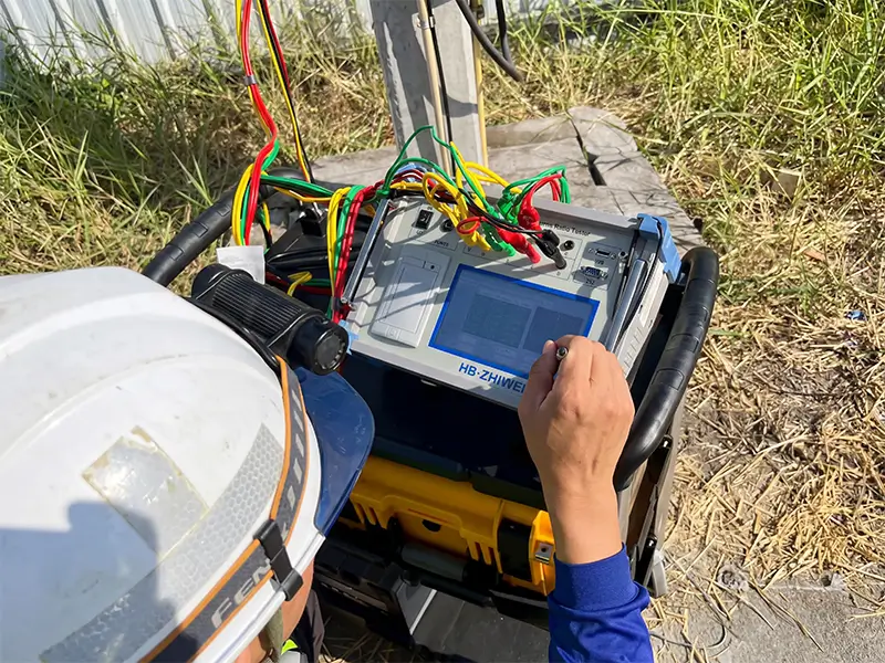
Step 4: Connect the TTR tester correctly (Grounding First)
- Reliable Grounding: First, securely connect the ground terminal (E) on the ZWBB201 panel to the substation’s grounding grid.
- Standard Wiring: Follow the “high to high, low to low” rule. Connect the high-voltage test cables (Yellow A, Green B, Red C, Black N) to the high-voltage bushings, and the low-voltage test cables (Yellow a, Green b, Red c, Black n) to the low-voltage bushings. Ensure the clips bite tightly and pierce through any oxide layer on the bushing terminals.
Step 5: Configure parameters on the screen and run the test
Use the ZWBB201’s 7-inch high-resolution touchscreen to input your parameters: high-voltage rated voltage, low-voltage rated voltage, total number of taps (enter 1 if it’s a single tap), tap step (e.g., 1.25%), and vector group.
Note: If the nameplate is blurry and the vector group is unknown, you can simply select “Unknown” on the ZWBB201. The instrument will use a smart algorithm to automatically analyze and determine the connection type.
Click the “Start” button.
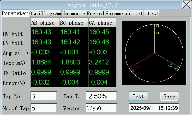
Step 6: Analyze the core diagnostic data on the screen
In just about 3 seconds, the ZWBB201 will complete the measurement. The screen will clearly display:
- Measured 3-Phase Ratio
- Ratio Error %
- Primary/Secondary Voltage and Phase Angle
- Excitation Current — This metric is highly useful for assessing the condition of the iron core.
Step 7: Cycle through all taps and export the data
Operate the tap changer, moving step-by-step from the lowest to the highest tap, repeating the measurement at each position.
The ZWBB201 automatically tracks the tap position and indicates the current tap point. After testing, insert a USB drive and click “Export” to save the complete database in Dbase3 format. You can open and print this report directly in Excel without installing any background software.
How to Professionally Interpret TTR Test Results? (The 0.5% Golden Rule)
According to the IEEE C57.12.90 international standard, the error between the field-measured ratio and the theoretical ratio calculated from the nameplate voltage should not exceed ±0.5%.
Anomalies Requiring High Alert:
- Error exceeds limits (>0.5%): This highly indicates a severe inter-turn short circuit in the winding.
- Extreme error in a single phase: This usually means there is an isolated fault in that specific phase’s winding or its corresponding tap changer contact.
- Abnormal unbalance in Excitation Current: Under normal conditions, A and C phases are slightly higher while B phase is lower due to the 3-phase core structure. However, if one phase’s excitation current suddenly spikes by hundreds of times, it generally points to core damage or a severe localized short circuit.
Field Expert Tips from Senior Engineers
Tip 1: Three-phase joint testing is key to avoiding human error.
Traditional single-phase instruments are slow, and heavily rely on frequent wire swapping. This easily leads to miswiring, causing short circuits or jumbled data. With the ZHIWEI ZWBB201, you connect all clips just once. The instrument switches internally via software, slashing work time and eliminating the root cause of human errors related to wire swapping.
Tip 2: Use “Waveform and Harmonic Analysis” for deep fault pinpointing.
If you notice data jumping during a test, the ZWBB201 allows you to tap the “Waveform” button mid-test to view primary and secondary voltage waveforms in real-time. You can also enter the “Harmonic Analysis” screen to view the 1st to 32nd harmonic distribution. This is extremely helpful for analyzing bad readings caused by high-frequency background harmonic interference from the grid or for identifying core saturation.
Tip 3: A quick fix for unstable readings or “Open Circuit” warnings.
When data jumps wildly in the field, 90% of the time it’s due to poor clip contact. Don’t immediately suspect a broken instrument. First, remove the clips, use a wire brush to scrub away the metal oxide layer on the bushing terminals, and firmly re-clamp them. This almost always solves the issue.
Tip 4: Watch out for residual magnetism messing with the phase angle.
If the ratio error is within the acceptable ±0.5% range, but the phase angle deviation is abnormal, the iron core likely has severe residual magnetism from a recent DC test (such as a winding resistance test). It’s recommended to run a transformer demagnetization routine before making your final TTR judgment.
EXPERT GUIDANCE
Need Help Choosing the Right Testing Equipment?
Frequently Asked Questions About TTR Testing
1. Can TTR testing be done while powered on (online monitoring)?
Absolutely not. TTR testing is a purely offline diagnostic test. It must be performed with the transformer’s main circuit fully powered off, isolated, discharged, and reliably grounded.
2. Our substation transformers are very old and the nameplates are entirely missing. Can we still test the turns ratio?
No problem. Using the adaptive feature of the ZHIWEI ZWBB201, simply select “Unknown” for the vector group. The instrument will automatically apply a standard sine wave signal (adaptive between 12-160V) to the unit. By capturing the primary and secondary voltage waveforms, it will automatically deduce the exact ratio and actual vector group.
3. Can this instrument be used to test Current Transformers (CT) and Potential Transformers (PT)?
Yes. The ZWBB201 supports both PT and CT testing. The setup for PTs is the same as for a single-phase transformer. For CTs, simply connect the instrument’s low-voltage side (a, c) to the CT’s primary side (A, X), and the instrument’s high-voltage side (A, C) to the CT’s secondary side (a, x) for precise polarity and ratio testing. Its measurement range goes up to 0.8–50,000, which is more than enough for various instrument transformer needs.
Upgrade Your Field Testing Operations — Manufactured by ZHIWEI
A successful substation TTR report is the result of combining strict field safety protocols, standardized SOPs, and high-precision testing equipment. Especially during tight windows like spring inspections, the smart features and anti-interference capability of your instruments directly determine your maintenance team’s throughput and diagnostic accuracy.
ZHIWEI (Baoding Zhiwei Electric Power Technology Co., Ltd.) has been deeply involved in insulation diagnostics and transformer testing for years. Our ZWBB201 Smart Transformer Turns Ratio Tester was developed specifically to solve the common pain points of traditional field testing: long test times, easy miswiring, and hard-to-manage data.
Say goodbye to tedious manual calculations and the risks of swapping wires. Contact us today at sales001@zhiweielectric.com or via WhatsApp (+8613833237336) to get the detailed ZWBB201 technical manual and live field demonstration videos. Equip your electrical testing team with the ultimate diagnostic tool!


