
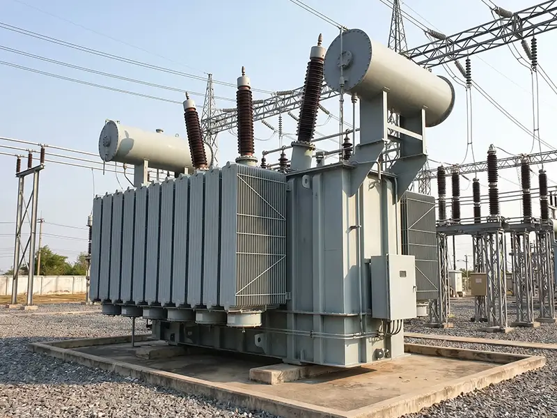
In the manufacturing acceptance and preventive maintenance of power transformers, generators, and instrument transformers, DC winding resistance testing is a core diagnostic step for evaluating winding insulation integrity and tap changer contact quality.
For equipment procurement managers and field test engineers, the most critical technical parameter when evaluating a DC resistance tester (or ohmmeter) is the output current. The output current specification not only determines the equipment’s procurement cost, but more importantly, it directly impacts field test accuracy, time consumed, and the engineering value of the final test data.
From an electrical principles perspective, this article will deeply analyze how output current affects DC resistance measurement and provide you with a scientific “equipment capacity matching” standard.
Table of Contents
The Underlying Logic of Output Current in DC Resistance Measurement
The core principle of DC resistance measurement operates on the classic Ohm’s Law (R=U/I). In practical industrial applications, the DC resistance of large transformer windings is extremely small, typically ranging from micro-ohms (μΩ) to milli-ohms (mΩ). This creates two major physical challenges during testing, and output current is exactly the key to solving them:
1. Overcome high winding inductance and drastically cut charging time
Transformer windings are virtually highly inductive loads. When a DC test current is applied, the inductance generates a strong back electromotive force (e=-Ldi/dt) to resist the change in current.
To capture a stable resistance reading, the test system must inject a large enough DC current to push the transformer core into magnetic saturation quickly. Once the core is saturated, the inductance (L) drops sharply, allowing the current to fully stabilize.
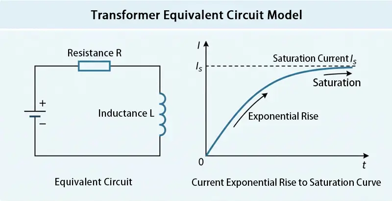
Engineering Insight: If the test current is too low, the charging time constant (τ=L/R) for a large 110kV main transformer will be huge. A single-phase test might force you to wait for tens of minutes. By pairing it with a properly large output current, the stabilization time can be compressed down to under a few dozen seconds.
2. Boost the signal-to-noise ratio for precise micro-ohm measurements
Substations are commonly plagued by heavy electromagnetic interference (EMI). Because the target resistance (R) is so small, an insufficient test current (I) will yield an overly weak voltage drop signal (U) across the windings (U=I×R), which can easily get drowned out by background electrical noise.
Applying a larger test current generates a distinct, high-voltage drop signal that greatly improves the Signal-to-Noise Ratio (SNR). This ensures the instrument’s A/D converter can accurately capture stable data, keeping the readings from bouncing around violently.
Core Selection Guideline: The 2% to 10% Rated Current Rule
When purchasing and running field tests, the test current is definitely not “the bigger, the better.” Authoritative industry standards (like IEEE C57.152) and veteran maintenance experience dictate that your test current should strictly follow this rule:
The test current should be kept between 2% and 10% of the tested transformer winding’s rated current.
Lower Limit (2%): Ensures the current packs enough energy to overcome the coil’s inductance, driving the core into deep saturation rapidly and sending a clear voltage signal back to the tester.
Upper Limit (10%): Strictly controls heat generation. According to Joule’s Law (Q=I²Rt), excessive current creates severe thermal effects inside thin wires. Under no circumstances should the absolute maximum test current exceed 15% to 20% of the rated current.
EXPERT GUIDANCE
Need Help Choosing the Right Testing Equipment?
Engineering Risks of Poor Test Current Selection
1. Current gear too low: A double loss in efficiency and accuracy
Data Drifting: The core never fully saturates, and lingering back electromotive force interferes with the micro-bridge system. As a result, the resistance reading on the screen continuously drifts, making it impossible to finalize a test report.
Misjudgment Risk: Weak measurement signals exponentially magnify the instrument’s relative error. This can easily mask actual early-stage defects, like internal broken winding strands or bad contacts in the On-Load Tap Changer (OLTC).
2. Current gear too high: Thermal effects cause major measurement errors
Copper has a positive temperature coefficient. For every 1°C increase in winding temperature, its resistance jumps by roughly 0.39%.
Calculation Formula: Rs=Rm(Ts+Tk)/(Tm+Tk)
(Note: the copper constant Tk=234.5).
If you wrongly apply a massive 50A test current to a small transformer, the windings will overheat instantly. The field reading (Rm) will be artificially inflated by the heat, heavily increasing the chances of a perfectly good transformer failing its Factory Acceptance Test (FAT).
Application Scenarios & Test Current Matching Guide
To help B2B buyers and testing engineers make informed choices, we’ve summarized typical equipment capacities and their ideal test currents:
| Equipment Type / Capacity Range | Recommended Test Current | Typical Applications |
|---|---|---|
| Voltage Transformers (PT), micro control motors | <1A | Lab testing, troubleshooting small coils in relay protection cabinets |
| 10kV Distribution Transformers (≤1600kVA) | 5A~10A | Industrial park distribution room maintenance, daily grid inspections |
| 35kV Power Transformers (≤8000kVA) | 10A~20A | Small/medium local substations, factory incoming power supply tests |
| 110kV and above Large Main Transformers | 40A, 50A, or up to 100A | Major hub substations, transformer manufacturing plant routine tests |
Best Choice: ZHIWEI ZW8110 DC Resistance Tester
Based on the guidelines above, a 10A output current is the sweet spot for testing 10kV to 35kV equipment. The ZHIWEI ZW8110 DC resistance tester is a professional-grade unit purpose-built for this exact requirement. The device brings three major advantages to the field:
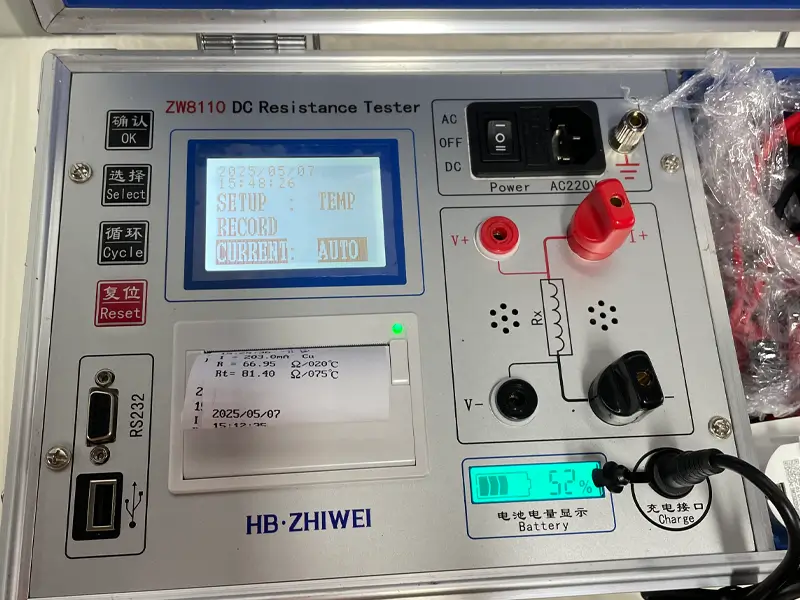
1. AC/DC Dual Power Supply: The ZW8110 is equipped with a high-capacity lithium battery. Even in remote areas or sites lacking 220V AC mains power, it can operate independently while maintaining a stable test current of up to 10A. This completely solves power-access headaches in the field and maximizes equipment runtime.
2. Smart Current Gear Adaptation: The tester supports manual multi-gear selection from mA up to 10A, alongside a core “Auto” mode. The built-in microprocessor automatically detects load inductance and resistance, dynamically dispensing the optimal test current. This prevents both low-current data drift and high-current overheating, guaranteeing precise and stable results.
3. Automated Data Conversion and Reporting: Featuring a built-in temperature compensation algorithm, the user simply enters the live oil temperature, and the system instantly converts the measured resistance to a standard reference temperature (like 75°C) with one click. Paired with a built-in micro printer for on-the-spot reporting, it eliminates manual math and drastically cuts down field test time.
Frequently Asked Questions
1. For convenience, can I use a 50A tester to measure a small 10kV distribution transformer?
A: Absolutely not. If you use a fixed 50A massive current to test a delicate coil, the instant surge will cause severe overheating errors or even fry the equipment completely. You must manually downshift the current gear, or use a tester equipped with “Smart Gear Adaptation”.
To visually show how the “Smart Adaptation” and “Auto Conversion” features work in the real world, here is actual test data from our May 2026 factory inspection report for the latest ZW8110 model (see image below). The built-in printer recorded real-time performance across different states.
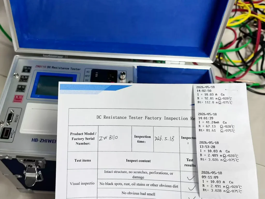
Testing Low Resistance: In Auto mode, the device output a solid 10.03A current, accurately capturing a minuscule transformer winding resistance of 2.489mΩ. It immediately auto-converted the figure right on the spot to its 75°C rated resistance equivalent of 3.028mΩ.
Testing High Resistance: When hooked up to a high-resistance load, the device smoothly and safely downshifted to the 41.24mA micro-current gear, giving a pinpoint 67.13Ω reading.
A multi-gear tester like this, handling everything from mA up to 10A, strikes the perfect balance between safety and precision. But again, mistakenly firing a 50A fixed current into those small coils will effortlessly burn out the test subject.
2. Since the test current is high, will the residual magnetic field affect subsequent tests?
A: Yes, it creates residual magnetism. A strong DC test will leave heavy residual magnetism in the transformer core, which inflates the inrush current during energization and messes with subsequent AC withstand voltage or no-load tests. Therefore, picking a premium tester with an auto-demagnetization feature is crucial.
Conclusion and Professional Advice
When shopping for a DC resistance tester, output current isn’t just a factor in the price tag—it is the central engineering parameter that balances “efficiency,” “data precision,” and “equipment safety.” Blindly chasing massive current limits wastes budget and risks thermal errors, while under-sizing the current leaves testing teams stranded waiting for drifting numbers. The smartest procurement strategy is to strictly abide by the 2%~10% rated current rule and match it directly to your field transformer capacities.
Beyond Equipment: Your Partner in Reliable Testing
We believe you deserve more than just a piece of testing equipment—you need a reliable technical partner. Backed by over a decade of industry experience, ZHIWEI is deeply dedicated to the R&D and manufacturing of high-voltage electrical testing equipment.
Just like the factory inspection report shown above, every single unit we ship (like the ZW8110) must survive a grueling Factory Acceptance Test. This isn’t just a multi-gear precision verification; it encompasses over 10 comprehensive checkpoints, from printer module testing and grounding safety checks down to unusual noise troubleshooting, ensuring it performs flawlessly right out of the box.
Not sure which output current or specific model fits your upcoming projects? Let’s skip the guesswork. Reach out to the ZHIWEI here. Tell us about the transformers you work with, and we’ll help you pin down the exact specs that make sense for your field scenarios.