
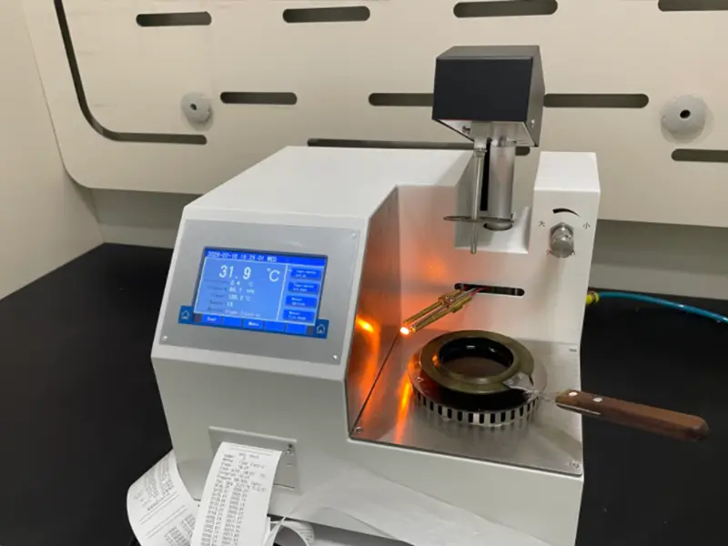
The flash point of insulating oil is a critical indicator for assessing the operational safety of power equipment such as transformers. Whether using the closed-cup method (ASTM D93) or the open-cup method (ASTM D92), when test results are abnormal (especially a significantly lowered flash point), it signals potential risks.
This article delves into the root causes of abnormal insulating oil flash point test results and provides a systematic troubleshooting process to help technicians accurately identify problems and ensure equipment safety.
Why is the Flash Point of Insulating Oil a Concern?
In power systems, transformers are irreplaceable core components, and insulating oil is the “lifeblood” for their safe operation. Its primary functions are insulation and cooling. The flash point, defined as the lowest temperature at which the oil vaporizes to form a flammable mixture with air that can momentarily ignite upon contact with a flame, is the foremost safety indicator for evaluating its fire hazard.
A significantly reduced flash point not only means a sharp increase in the risk of fire and explosion but also serves as a strong “alarm signal,” suggesting that the insulating oil may be contaminated, the oil has degraded, or there are serious latent faults within the transformer. Therefore, accurate testing and correct interpretation of flash point data are of paramount importance.
Core Concepts: Closed-Cup vs. Open-Cup Flash Point
Before analyzing anomalous cases, we must understand the differences between the two mainstream testing methods:
| Feature | Closed-Cup Flash Point | Open-Cup Flash Point |
|---|---|---|
| Principle | The oil sample is heated in a sealed test cup, where vapors accumulate in a confined space, reaching a flammable concentration more easily. | The oil sample is heated in an open container, allowing vapors to diffuse freely into the surrounding air. |
| Characteristics | Test results are typically lower and are extremely sensitive to light, volatile contaminants (such as fuel oil, solvents). Therefore, it is widely used to detect contamination in insulating oil. | A higher temperature is required for the vapors to reach a flammable concentration, so its test results are typically higher. In addition to the flash point, this method can also determine the fire point (the temperature at which combustion is sustained for at least 5 seconds). |
| Primary Use | Assessing fire safety hazards and detecting oil contamination. | Primarily used for assessing the thermal stability and fire hazard of non-volatile oils (like lubricating oils). |
Key Difference: Due to its enclosed structure, the closed-cup method is far more sensitive to contaminants than the open-cup method, making it a better choice for diagnosing the health of insulating oil.
Typically, there is a difference of a few degrees Celsius between the closed-cup and open-cup flash points of new oil. However, if the difference is substantial or the closed-cup flash point is abnormally low, it must be treated with high alert.
Analysis of Anomalous Cases: The “Three Main Culprits” for a Lowered Flash Point
When you find that the flash point test result of insulating oil is significantly lower than its factory specifications or historical data, the cause can usually be attributed to one of the following three categories:
Culprit One: Sample Contamination
This is the most common reason for a sharp drop in flash point. Even a very small amount of volatile contaminant can have a huge impact on the result.
Light Distillate Fuel Contamination: Leaks of diesel, gasoline, or jet fuel are the most critical. For example, just 0.5% diesel contamination can cause the flash point of insulating oil to plummet from 145°C to below 100°C.
Solvent Contamination: Cleaning agents, solvents, or other chemicals left over from equipment cleaning or maintenance get mixed into the oil.
Moisture Ingress: While moisture itself does not directly lower the flash point significantly, high water content is often associated with issues like poor sealing, which also creates opportunities for other contaminants to enter. At the same time, moisture severely reduces the oil’s dielectric strength.
Mixing of Oils: Accidentally mixing low-flash-point, low-viscosity oils (such as regular motor oil) into the transformer during oil top-up or replacement.
Oil Aging and Cracking: Local overheating or discharge faults (such as arcing, corona) inside the transformer can cause thermal cracking of the insulating oil, producing low-molecular-weight combustible gases like hydrogen, methane, ethylene, and acetylene. These gases, dissolved in the oil, will significantly lower the flash point.
Culprit Two: Instrument and Equipment Issues
Instrument malfunction or improper setup is another important area to investigate.
Inaccurate Heating Rate: Whether using a manual or automatic instrument, the heating rate must strictly adhere to the standard (e.g., 5-6°C/minute for ASTM D93 Procedure A). Heating too quickly will cause the temperature measurement to lag behind the actual oil temperature, resulting in a lower measured flash point.
Ignition Source Problems:
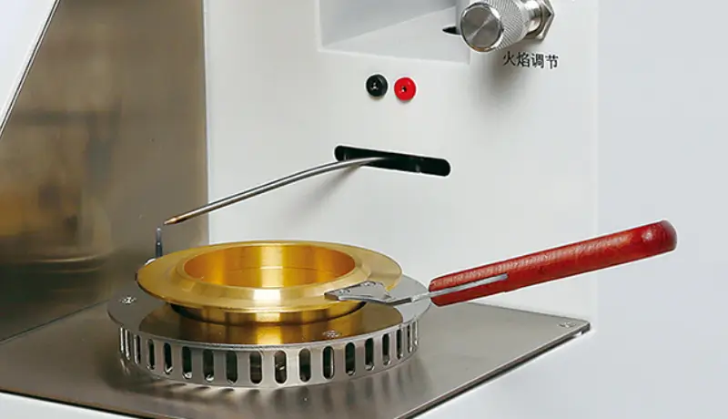
Improper Flame Size: The standard requires a flame diameter of 3.2-4.8 mm. An oversized flame will ignite the vapor prematurely, leading to a low result.
Electric Igniter Aging/Failure: Check if the electric igniter is malfunctioning.
Inaccurate Temperature Sensor: The accuracy of the thermometer is crucial. Any deviation will directly lead to incorrect flash point readings.
Barometric Pressure Not Corrected: The flash point changes with atmospheric pressure. The higher the altitude, the lower the atmospheric pressure, and the lower the flash point. Professional flash point testers should have an automatic barometric pressure compensation function; otherwise, manual correction is required.
Improper Instrument Cleaning: Residue from the previous test sample (especially a low-flash-point sample) on the test cup, lid, or stirrer will contaminate the new sample.
Culprit Three: Procedural Errors
The human factor cannot be ignored, especially in manual or semi-automatic testing.
Improper Sampling: Failing to obtain a representative oil sample from the correct location on the transformer (e.g., the bottom valve), or using an unclean sampling container.
Improper Sample Handling: The sample is exposed to the air for a long time before testing, causing light components to evaporate or become contaminated by the environment.
Non-compliant Stirring Speed (Closed-Cup Method Only): Stirring is intended to ensure uniform sample temperature and promote vapor generation, but a speed that is too fast or too slow will affect the vapor concentration, thereby affecting the result.
Insufficient Understanding of the Standard: The operator fails to strictly follow every detailed step specified in the ASTM D93 or D92 standard.
Systematic Troubleshooting Procedure
When faced with an abnormal flash point test result, follow this four-step troubleshooting method:
Step 1: Result Verification and Re-checking
Immediate Retest: Use the same oil sample to perform a second test immediately. If the result returns to normal, it might have been a one-time operational error or an incidental instrument issue.
Retest with a New Sample: If the retest result is still abnormal, a new sample should be taken from the transformer for testing to rule out the possibility of contamination during the sampling process.
Step 2: Comprehensive Instrument Inspection
Calibrate with a Reference Material: This is the most critical step. Use a certified reference material (CRM) with a known flash point value to verify the instrument. If the CRM test result deviates beyond the allowable range, it proves that the instrument has a problem.
Check Key Components:
Cleanliness: Thoroughly clean the test cup, lid, stirrer, and temperature probe.
Ignition System: Check the size of the gas flame or the working status of the electric igniter.
Temperature Probe: Check the probe for any damage and ensure it is installed in the correct position.
Verify Instrument Settings: Confirm that the correct test procedure has been selected (e.g., Procedure A, B, or C for ASTM D93) and that parameters like the heating rate are set correctly.
Step 3: In-depth Analysis of the Insulating Oil
If the instrument calibration is correct, the problem most likely lies with the oil itself. At this point, correlational diagnostic tests are needed:
Viscosity Test: Fuel contamination will significantly reduce the viscosity of the insulating oil. This is very strong cross-verification evidence.
Dissolved Gas Analysis (DGA): This is the “gold standard” for diagnosing internal faults in a transformer.
| Dissolved Gas | Indicated Fault Type |
|---|---|
| C2H2 | High-energy arcing |
| C2H4, CH4 | Severe overheating |
| H2 | Partial discharge, corona |
These fault-generated gases dissolving in the oil are the direct cause of the lowered flash point.
Moisture Content Test: Check if the moisture in the oil exceeds the standard limit to assess whether there are sealing problems.
Step 4: Evaluate the Transformer Body
Check Historical Records: Review the maintenance, oil top-up, and repair records of the equipment to look for any abnormal operations.
External Inspection: Conduct a visual inspection of the transformer for signs of oil leaks, bushing damage, etc.
Infrared Thermal Imaging: Use an infrared camera to scan the exterior of the transformer to find any abnormal hot spots, which may be related to internal overheating.
Typical Anomalous Cases and Handling
Case A: Closed-Cup Flash Point is 30–50°C Too Low
Phenomenon: The historical value for the same batch of oil is around 165°C, but the current measurement is 120–130°C.
Troubleshooting:
Use a new, clean, and dried test cup.
Take a new sample in a new, dried, and sealed glass bottle; let it sit for 15 minutes to remove bubbles.
Check the elasticity and surface of the sealing ring; replace if cracked.
Verify the instrument with “standard flash point oil.”
After retesting, the result returned to 160°C ±2°C.
Conclusion: The original sampling bottle was not completely dry after cleaning, and a small amount of residual solvent caused the low reading.
Case B: No Flash Occurs in Open-Cup Method
Phenomenon: The temperature reached 180°C, but no flash was observed.
Troubleshooting:
Check the test flame height and adjust to the specified height (typically 3–4 mm, refer to the standard).
Shield from drafts (use a windscreen, turn off direct air conditioning).
Increase the sample volume to the specified mark.
Perform a quick verification with standard oil.
Check the gas source and igniter; clean carbon deposits from the nozzle.
Conclusion: The flame height was too low + draft interference, resulting in no flash.
Case C: Poor Repeatability (Difference >10°C for three tests on the same sample)
Phenomenon: Three closed-cup results: 152°C, 161°C, 150°C.
Troubleshooting:
Standardize sample handling (settling time, volume, stirring speed according to the standard).
Check if the heating rate curve is stable.
Clean/replace the photoelectric flame detection probe or window.
Check the stirrer’s rotation speed and operating sound (stabilized after replacing the micro-motor bearing).
Conclusion: A combination of an unstable stirrer and a contaminated photoelectric probe.
Case D: Temperature Display Deviation (10°C difference from standard oil)
Phenomenon: The nominal value of the standard oil is 150°C, but the measured value is about 160°C.
Troubleshooting and Correction:
Perform a multi-point temperature calibration using a dry block or oil bath (e.g., at 100°C, 150°C, 200°C) and record the deviations.
Apply a deviation correction to the probe or replace the probe.
Verify that the heating rate is within the standard tolerance.
Conclusion: The temperature probe aged, causing a systematic high bias.
Standardized Troubleshooting Procedure (Can be used for SOP)
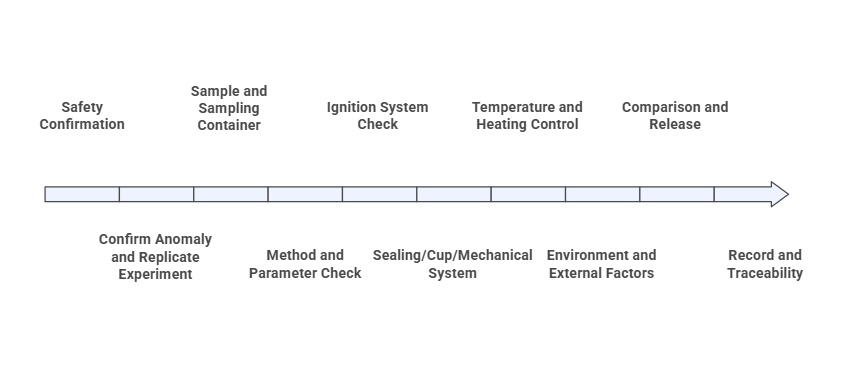
Recommended sequence: first, personnel and equipment safety; then sample and method; finally, instrument hardware and calibration.
Step 1: Safety Confirmation
Stop heating, turn off the gas source, and wait for the temperature to drop to a safe level before operating.
Ensure good ventilation, have a fire extinguisher ready, and avoid open flames and sparks.
Wear protective gloves/goggles to prevent burns from hot oil and inhalation of oil mist.
Step 2: Confirm Anomaly and Replicate Experiment
Identify the issue: too low/too high/no flash/poor repeatability/unstable temperature control.
Retest at least twice using the same method parameters (program, heating rate, stirring, ignition interval).
Compare with historical records or a control sample (standard oil) to determine if it’s a sample issue or an instrument issue.
Step 3: Sample and Sampling Container
Use clean, dry, and sealed containers; avoid plastic containers whose volatiles might interfere.
Ensure sufficient sample volume, let it sit for 15–30 minutes to eliminate bubbles, and avoid water droplets/condensation.
If contamination is suspected, take a new sample and perform an “on-site comparison” (original vs. new sample).
Step 4: Method and Parameter Check
Confirm the selected standard and procedure (e.g., ASTM D93 Procedure A/B/C).
Check heating rate, ignition interval, stirring speed, and flame height; restore to standard default values.
Verify if the liquid level/sample volume reaches the mark.
Step 5: Ignition System Check
Check gas source pressure, pressure reducer, hose leaks, and nozzle carbon deposits; adjust the flame to the standard height.
Clean and adjust the gap of the electric igniter; ensure secure wiring connections.
Clean the window of the flame detector (optical/thermal) and test its sensitivity.
Step 6: Sealing/Cup/Mechanical System (especially for closed-cup method)
Check the cup-rim seal, lid clamping force; replace aged O-rings.
Calibrate the stirrer speed, diagnose any abnormal motor sounds; ensure the cup is clean and unscratched.
For the open-cup method, install a windscreen to ensure no significant drafts.
Step 7: Temperature and Heating Control
Perform multi-point temperature calibration (e.g., at 100/150/200°C), correct deviations, or replace the probe.
Verify the heating rate using a stopwatch and the temperature record curve.
Check power supply stability (connect to a voltage stabilizer/UPS if necessary).
Step 8: Environment and External Factors
Keep away from air conditioner vents/door drafts; avoid direct sunlight.
In high-altitude areas, note the effect of atmospheric pressure and apply correction according to the standard or note the ambient pressure in the report.
Step 9: Comparison and Release
Verify once with standard flash point oil; simultaneously run parallel tests on the same batch of samples with two cups or two instruments.
If the instrument/method is confirmed to be normal, then decide whether to re-sample or reject the abnormal sample.
Step 10: Record and Traceability
Completely record parameters, environment, instrument status, maintenance actions, and results.
Provide a traceable evidence chain for internal and external audits.
Preventive Maintenance and Inspection Suggestions
Daily (Per Shift/Day)
- Clean the cup, lid, and sealing surfaces; ensure they are dry and free of solvent residue.
- Visually inspect the flame nozzle/igniter pin; perform one ignition test.
- Check the stirrer’s operating sound and speed display.
- Record ambient temperature and note any draft interference.

Monthly/Quarterly
- Multi-point temperature calibration and record archiving.
- Check gas line integrity, pressure reducer status, and clean carbon from the nozzle.
- Comparison test: Compare with a peer instrument or an external lab.
Frequently Asked Questions
1. Closed-cup and open-cup results are inconsistent. Which one is correct?
The two methods have different purposes and scenarios. The closed-cup is more sensitive, while the open-cup is closer to open environmental conditions. The judgment should be based on the procurement contract/applicable standard; avoid mixing up their thresholds.
2. What to do when testing at high altitudes?
Apply a barometric pressure correction according to the standard used, or note the ambient pressure conditions in the report, and confirm with a standard oil for local comparison.
3. Can alcohol be used to clean the test cup?
Yes, but it must be dried thoroughly. It is not recommended to use large amounts of fast-evaporating solvents immediately before a test. A dedicated neutral cleaning agent followed by drying is a better alternative.
4. What range of result fluctuation is considered normal?
Refer to the repeatability/reproducibility requirements of the standard being used. Also, consider the laboratory’s internal control limits (established from historical proficiency testing and trend analysis).

Conclusion: Turning Data into Action
The stability of insulating oil flash point testing relies on compliant method parameters and sample management, as well as on details like ignition, sealing, temperature control, and environment.
By following a layered troubleshooting process—“safety first, then sample, then parameters, then hardware, and finally calibration”—and performing routine preventive maintenance, most anomalies can be located and resolved quickly.
It is recommended to establish an in‑house anomaly database and trend charts, incorporating typical cases and solutions into SOPs and training courses to continuously improve the laboratory’s repeatability and compliance capabilities.
Regular, standardized flash point testing, combined with other oil analysis methods such as DGA and viscosity, is a core element in achieving condition‑based maintenance for transformers, extending equipment life, and ensuring the safe and reliable operation of the power grid.
Want to learn more about advanced solutions for insulating oil testing? Contact us now to keep your equipment operating in the safest condition!


